Fuselage Part Two
Welcome to Fuselage part two, this is a continuation of the fuselage part of the build. Fuselage Part One was getting quite large and the page was loading slowly so I added this page to help speed things up.... |
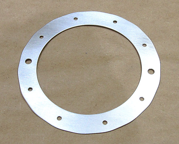
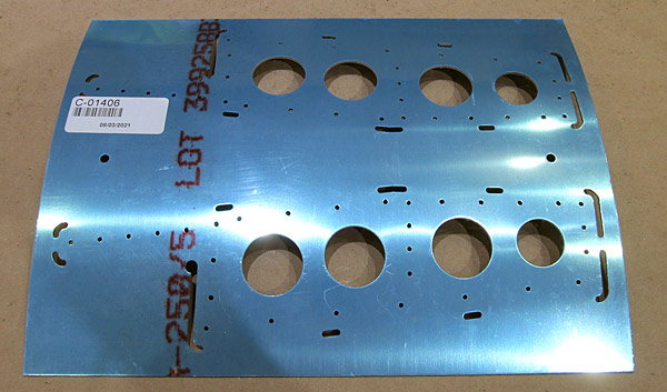
 I am deburring parts listed in Section 42: Miscellanea which are basically access panels that are located in the center of the fuselage cabin interior. |
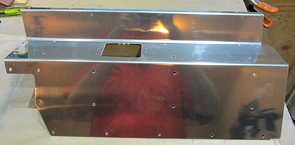
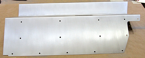
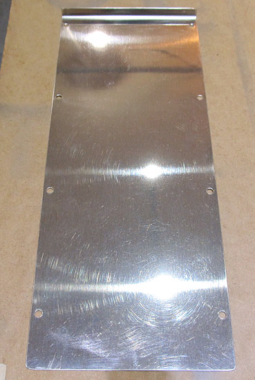
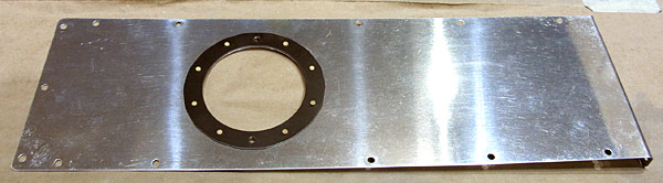
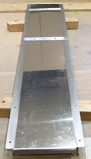
 This is the "door" that separates the baggage compartment from the aft section of the fuselage. |
 After the (F-01406F) baggage bulkhead corrugation is painted, a placard to warn passengers as to the experimental nature of this aircraft, will be placed on it to comply with FAA regulations 45.23. |
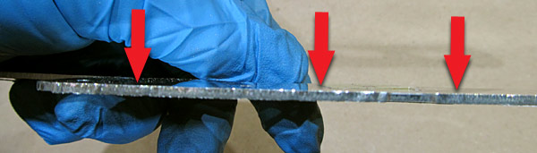
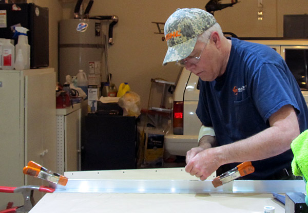 I like to use a hand file to debur the edges of parts first and follow up with sanding or polishing the edges with fine grit sand paper. It also helps to have the part clamped to the bench! |
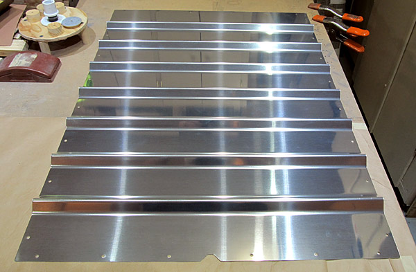
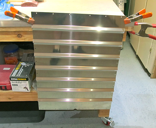
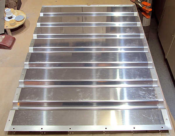
 The debur process is done and now I have scuffed the front side with maroon Scotch-Brite™ pads in preparation for painting. |
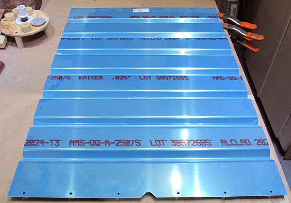
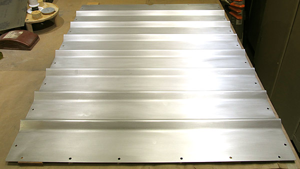
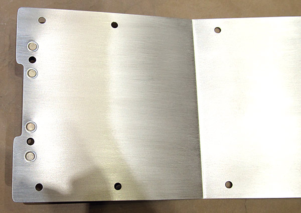
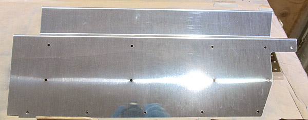
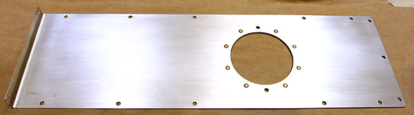
 This is the aft side of the (F-01406F) baggage bulkhead corrugation. I am only going to paint the edges and the remainder will be the natural aluminum finish. |
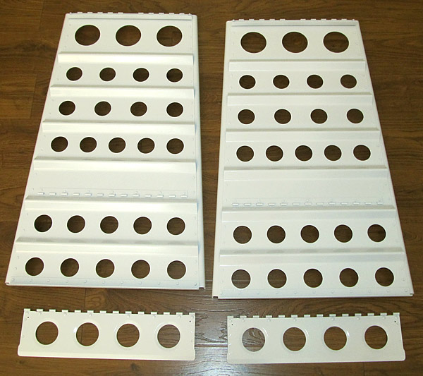
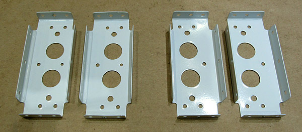
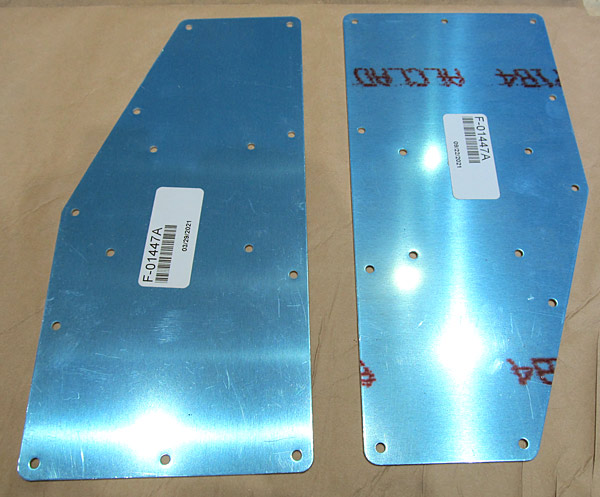 The next parts to be debuured are the (F-01447A) step access covers, there are two of them. These cover the baggage floor section where the aircraft steps are installed. |
 All of the edges of the (F-01447A) step access covers have been deburred and all of the holes have been deburred. |
 I scuffed the (F-01447A) step access floor covers with maroon Scotch-Brite™ pads in preparation for painting. |
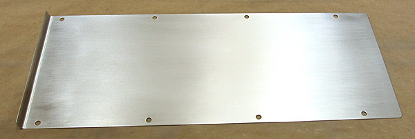
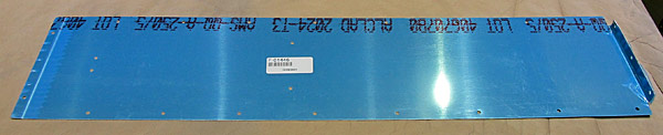 The (F-01446) baggage floor cover is next for deburring. |
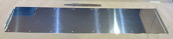 The edges of the (F-01446) baggage floor cover have been deburred and all of the holes have been deburred. |
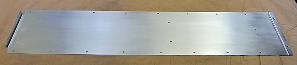 The outer surface of the (F-01446) baggage floor cover has been scuffed with a maroon Scotch-Brite™ pad in preparation for painting. |
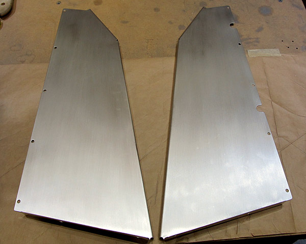
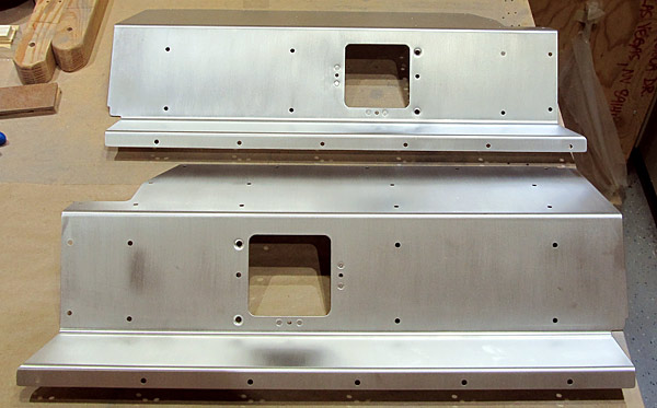
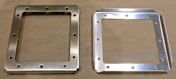
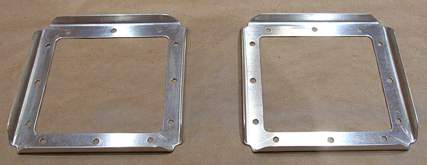
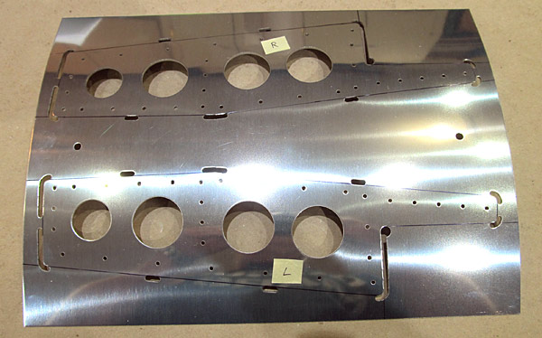
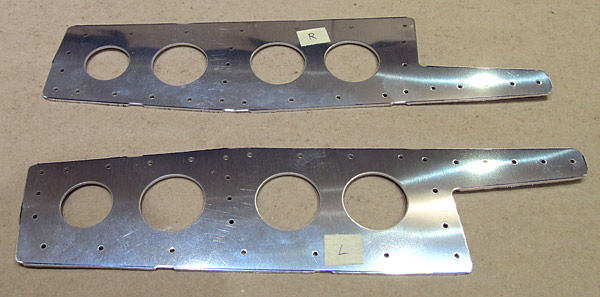
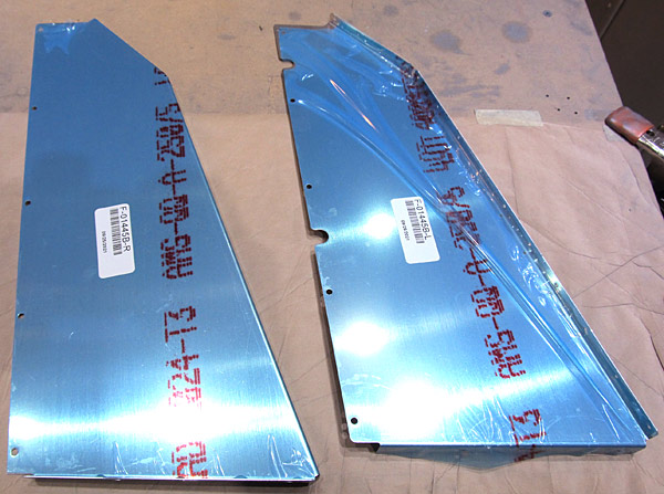 The (F-01445B-L and F-01445B-R) left and right flap motor cover sides are next to be deburred. |
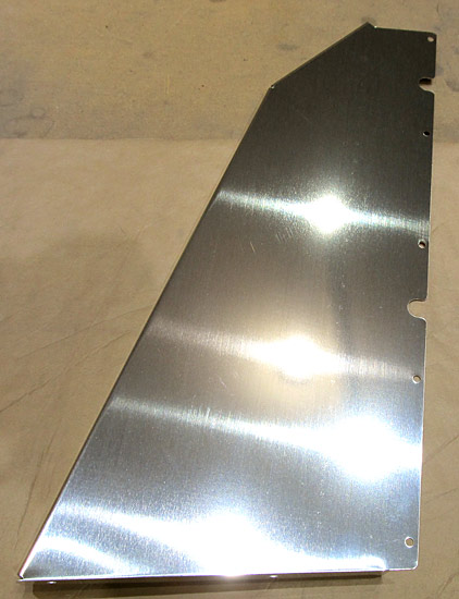 I started deburring the edges of the (F-01445B-R) right flap motor cover. The edges have been deburred here as well as all of the screw holes. |
 I scuffed the outer surface of the (F-01445B-R) flap motor cover with a maroon Scotch-Brite™ pad in preparation for painting. |
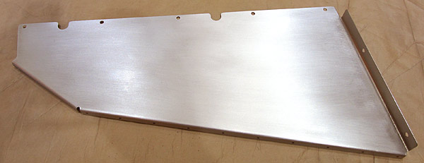
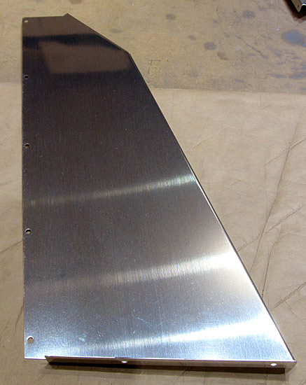 I deburred the edges of the (F-01445B-L) flap motor cover and deburred all of the screw holes. |
 The outer surfaces of the (F-01445B-L and F-01445B-R) left and right flap motor covers with a maroon Scotch-Brite™ pad in preparation for painting. |
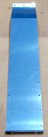 The (F-01445A) front flap motor cover is next to be deburred. |
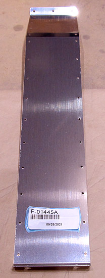 The (F-01445A) front flap motor cover edges have been deburred and all of the screw holes have been deburred. |
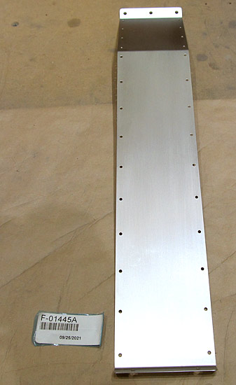 I scuffed the outer surface of the (F-01445A) flap motor cover with a maroon Scotch-Brite™ pad in preparation for painting. |
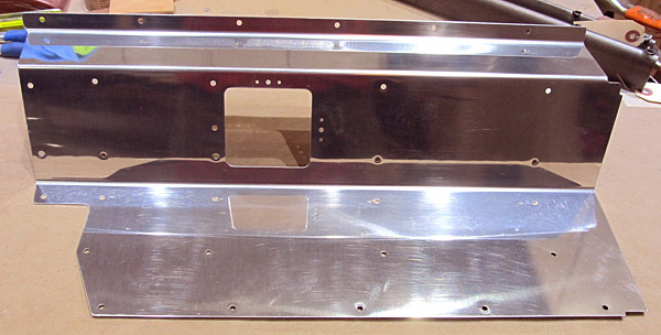
 The flap motor cover assembly consists of three pieces, the (F-01445B-L and F-01445B-R) left and right flap motor cover sides, and the (F-01445A) flap motor cover front. |
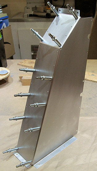 I clecoed the (F-01445B-L and F-01445B-R) left and right flap motor cover sides to the (F-01445A) flap motor cover front. |
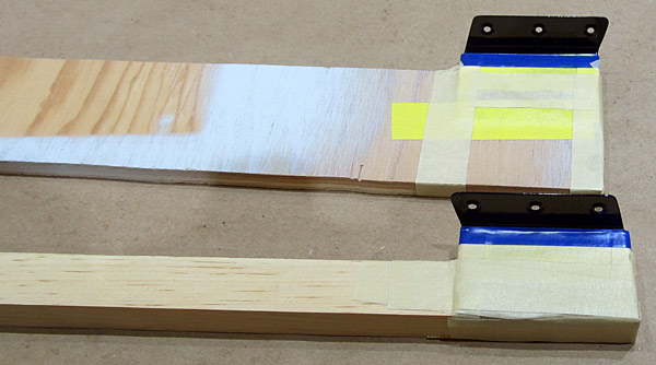
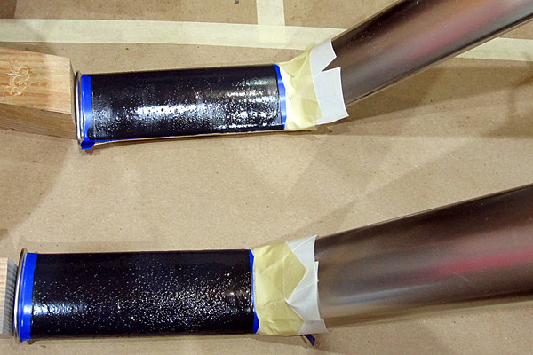
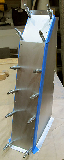 I am placing blue masking tape along the overlapping edges of the flap motor assembly so that when I disassemble the unit I can prime them. |
 I have disassembled the flap cover assembly and will prime the edges with SPI 6610-4 epoxy primer. |
 I just painted the edges with a coat of SPI 6610-4 epoxy primer using a brush, nothing fancy here; it will never be seen! |
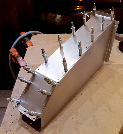 As per step three, on page 42-03, referencing figure three, the (F-01445B-R, F-01445B-L, and F-01445A) flap motor covers were clecoed together and riveted using AN470AD3-3 rivets set with a rivet gun and tungsten bucking bar. |
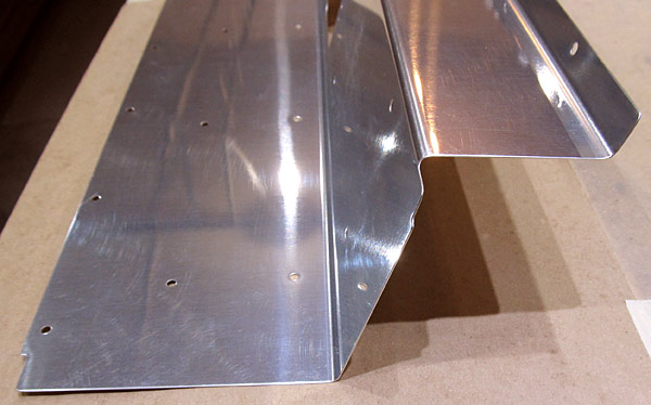
 View of the inside of the flap motor cover assembly. |
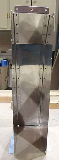
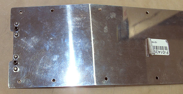
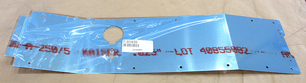 The (F-01439) seat ramp cover is next to be deburred. |
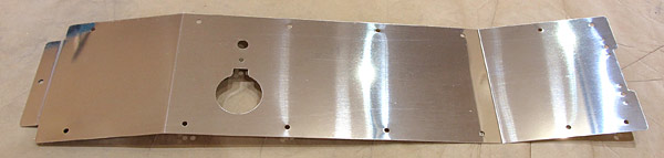 The (F-01439) seat ramp cover edges have been deburred as were all of the screw holes. |
 The outer surface of the (F-01439) seat ramp cover was scuffed with a maroon Scotch-Brite™ pad in preparation for painting. |
 As per step two, on page 42-02, referencing figure one, four nutplate rivet holes in the (F-01439) seat ramp cover were dimpled to receive AN426AD3-3 rivets. |
 I used our DRDT2 dimple machine to dimple the holes with 3/32" dimple dies. |
 (K1000-08D) nutplates will be installed here. They are pre-dimpled in order to receive the (AN426AD3-3) rivets. |
 As per step two, on page 42-02, the (K1000-08D) nutplates were installed using our hand squeezer. |
 Just a closer view. |
 View from the back side of the (F-01439) seat ramp cover nutplate installation. |
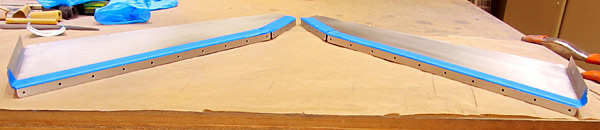
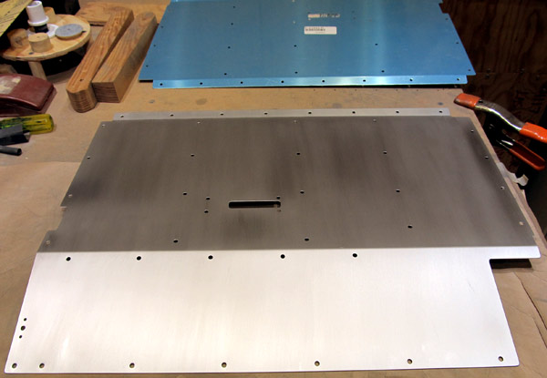
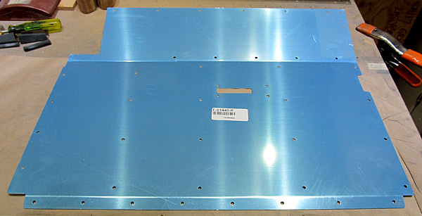
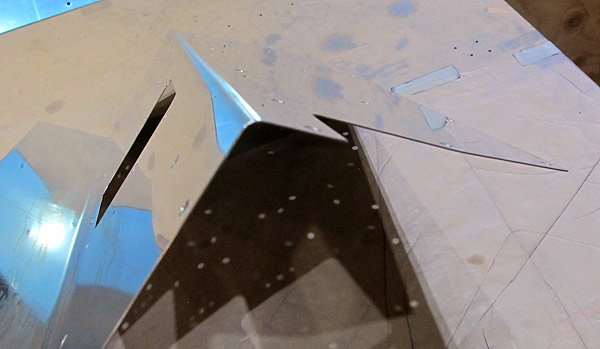
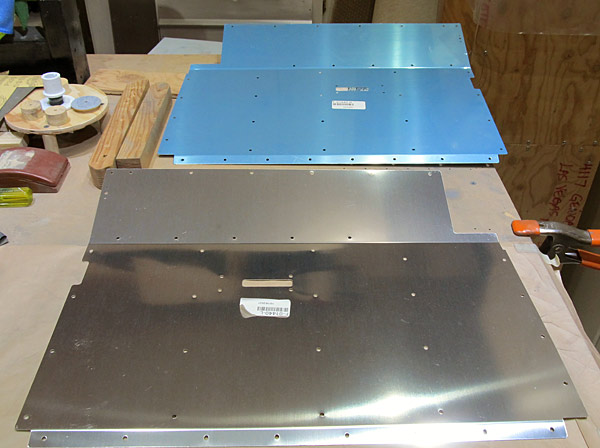 There are two seat ramps, (F-01440-L and F-01440-R). They are the at base of the front seats. |
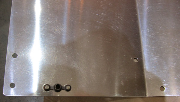
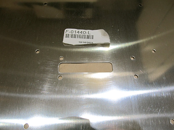 Since the crotch strap is passed through this slot, I made sure that the edges of the slot were rounded over so as to not have a point where abrasion could occur. |
 I scuffed the outer surface of the (F-01440-L) left seat ramp with a maroon Scotch-Brite™ pad in preparation for painting. |
 As per step one, on page 42-02, referencing figure one, the nutplate rivet holes in the (F-01440-L) left seat ramp were dimpled to accept AN426AD3-3 rivets. |
 The K1000-08D nutplate was riveted to the (F-01440-L) left seat ramp with AN426AD3-3 rivets set with our hand squeezer. |
 Top view of nutplate rivets set on the (F-01440-L) left seat ramp. |
 View of nutplate on the back side of the (F-01440-L) left seat ramp. |
 Next, on to the deburring process of the (F-01440-R) right seat ramp. Just like the left seat ramp, this panel is at the base of the seat on the right side of the aircraft. |
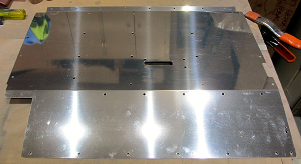 The edges of the (F-01440-R) right seat ramp and all of the screw holes were deburred. |
 The edges were polished on this (F-01440-R) right seat ramp, (as they are on all of my deburring operations), using fine grit sandpaper. |
 I scuffed the outer surface of the (F-01440-R) right seat ramp with maroon and gray Scotch-Brite™ pads and washed all surfaces with acetone in preparation for painting. |
 As per step one, on page 42-02, referencing figure one, I dimpled the nutplate holes in the (F-01440-R) right seat ramp in order to receive AN426AD3-3 rivets using 3/32" dimple dies set with our DRDT2 dimple machine. |
 As per step one, on page 42-02, referencing figure one, I riveted the K1000-08D nutplates to the (F-01440-R) right seat ramp with AN426AD3-3 rivets using our hand squeezer. |
 Here is the view of the riveted K1000-08D nutplate on the back side of the (F-01440-R) right seat ramp. |
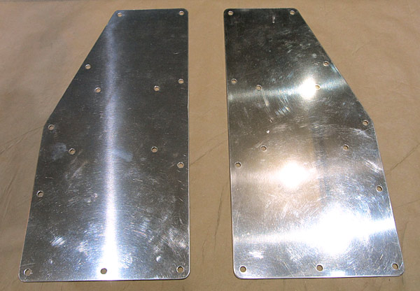
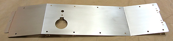
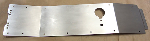
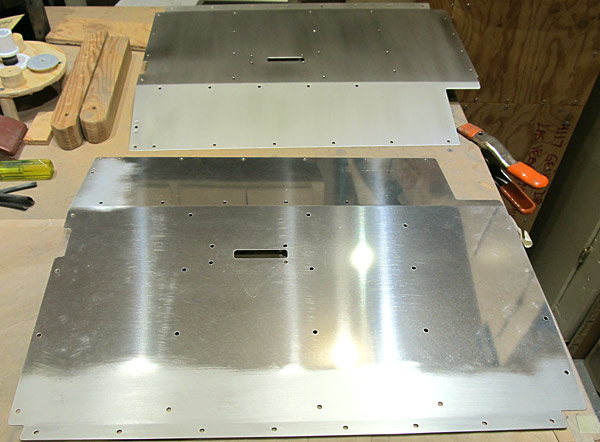
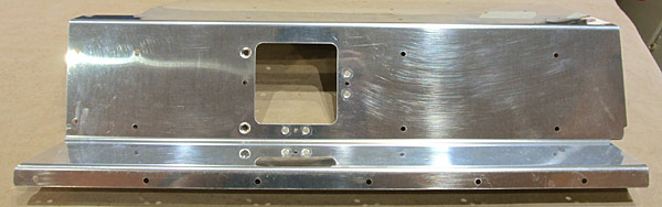
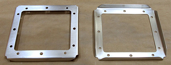
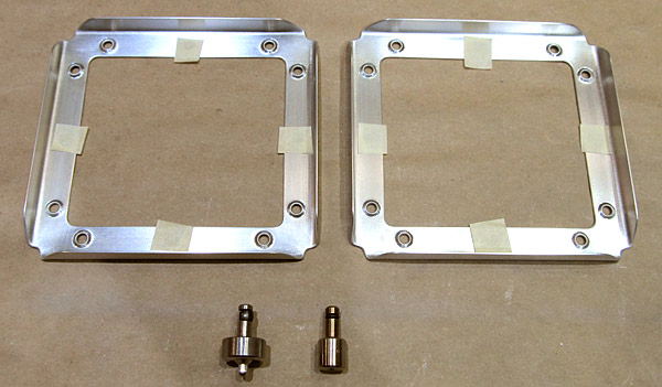
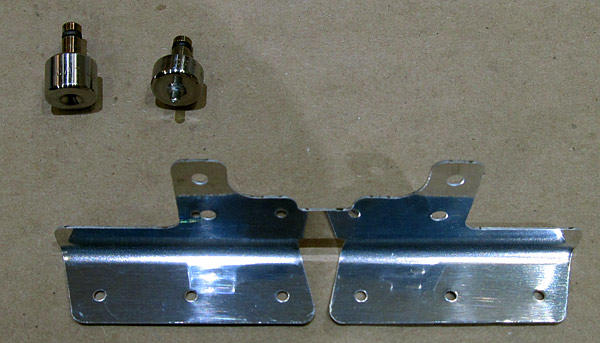
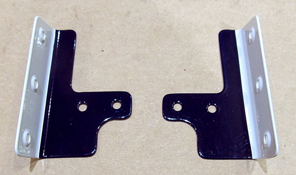
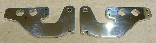
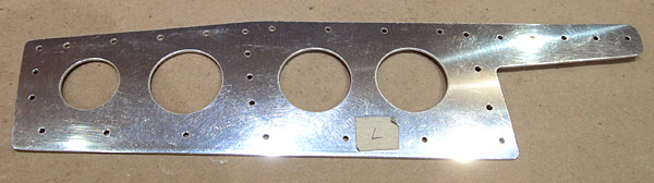
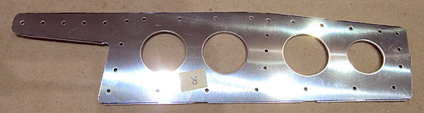
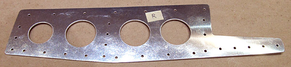
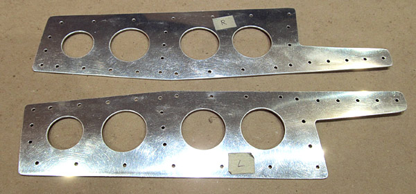
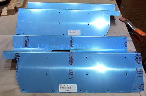 These are the (F-01436-L and F-01436-R) left and right control column covers. They are next for deburring. |
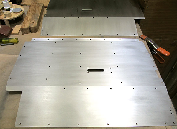
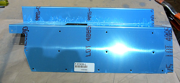 I am starting on the (F-01436-L) left control column cover. |
 I deburred the edges and all of the holes in the (F-01436-L) control column cover using a file. |
 After the file work is done I like to polish the edges of the pieces with fine grit sandpaper. I usually start with 220 grit sandpaper and finish with 600 grit. |
 Nice! |
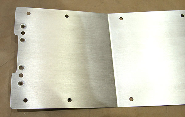
 I scuffed the outer surface of the (F-01436-L) left control column cover with maroon and gray Scotch-Brite™ pads in preparation for painting. |
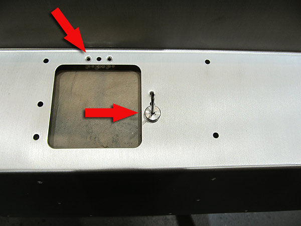
 This is the part where I am a little embarassed about....there are four holes that need to be dimpled in order to install nutplates. The "throw" on our hand squeezer is 3 inches and it will not reach the two holes located at the back of the (F-01436-L) left control column cover because of the bend (almost 90°) in the piece and I can't get it into the opening to get at the holes.....what am I going to do? |
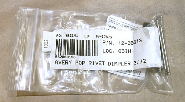
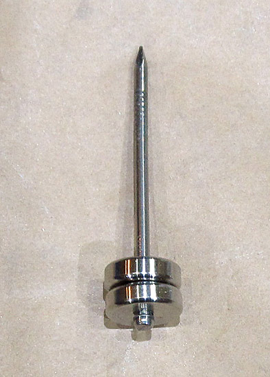 The Avery pop rivet dimpler has a male and female 3/32" dimple die set and uses a hardware nail (4D I think) as the mandrel that an ordinary pop rivet gun will use to make the dimple. |
 You just slip the female die and mandrel through the bottom of the metal that needs to be dimpled and the male dimple die will be placed over the mandrel on the opposite side. |
 Make sure everything is snug. |
 Now on the other side the male dimple die gets placed onto the nail mandrel. |
 As you can see, the dimples turn out nice. |
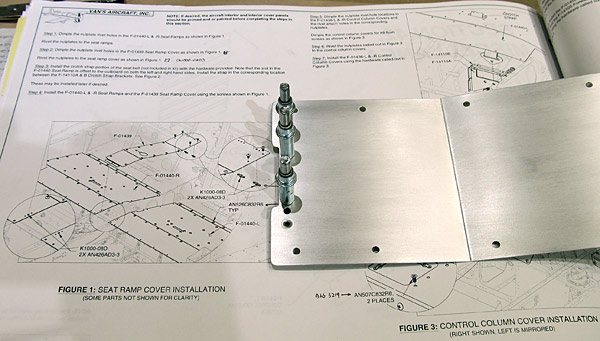
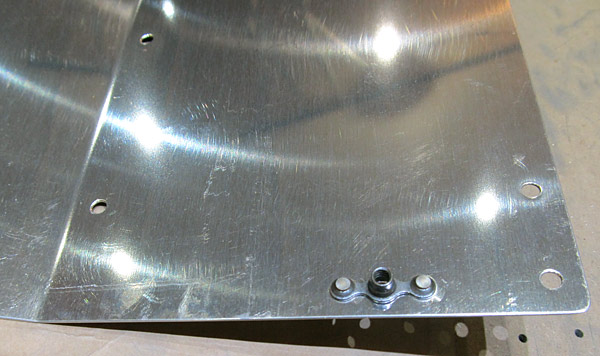
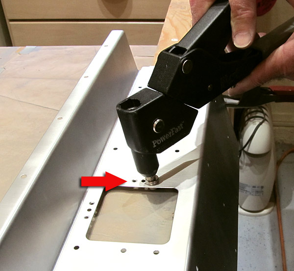 As per step five, on page 42-02, referencing figure three, I dimpled the four rivet holes on the (F-01436-L) left control column cover that will receive AN426AD3-3 rivets using the Avery 3/32" pop rivet gun dimple tool. |
 Now the next hurdle....how do I dimple the #8 screw holes? I don't have a #8 pop rivet gun dimple tool, (I still haven't figured it out that I have a 1.5" yoke for the hand squeezer) that will easily do the job. |
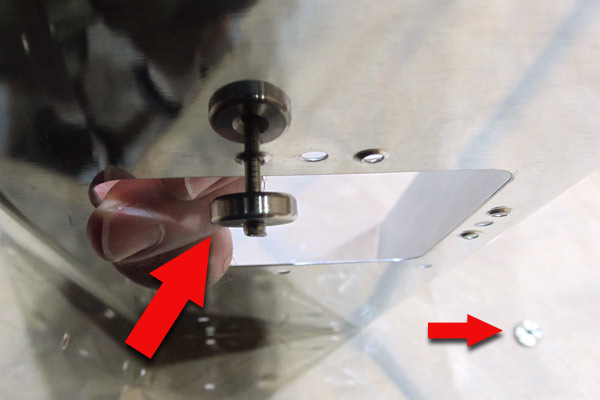
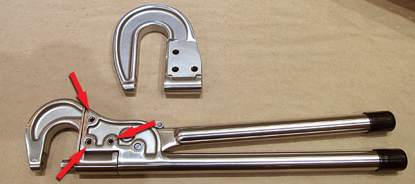
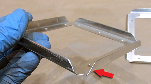
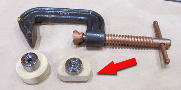 This is the apparatus that I constructed in order to dimple the #8 screw holes that are in the hard to reach areas of the (F-01436-L) left control column cover. |
 As per step five, on page 42-02, referencing figure three, I dimpled the remaining #8 screw hole on the (F-01436-L) left control coulmn cover with the "C" Clamp device. |
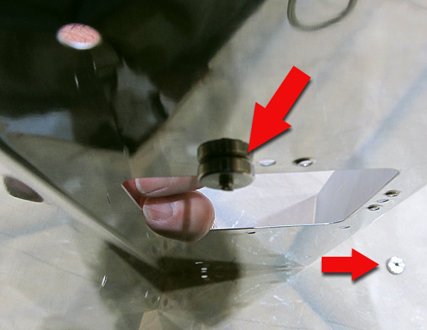
 Here is what it looks like when viewing from above, you can also see why I made the one wood dimple die holder semi-circular because the edge does get a little close to the bend in the metal of the (F-01436-L) left control coulmn cover. |
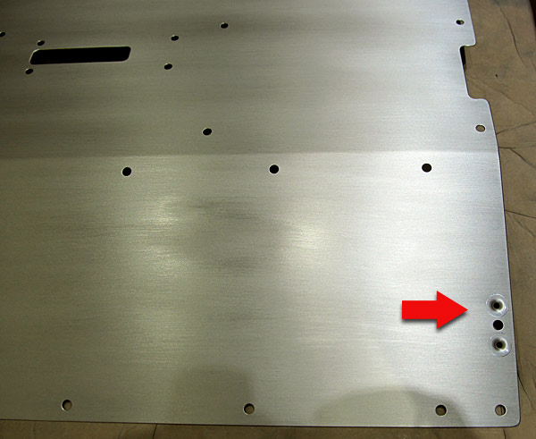
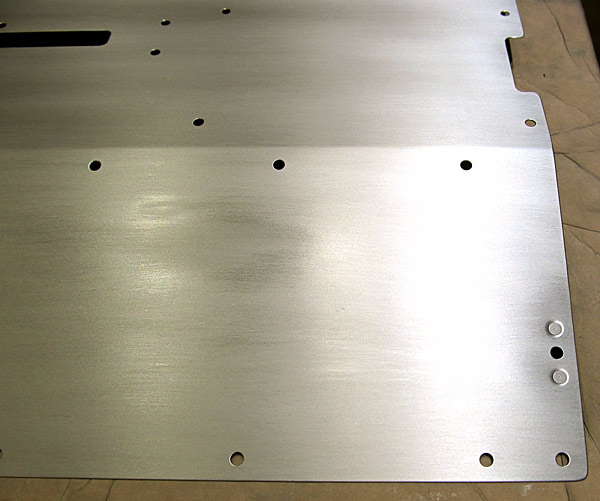
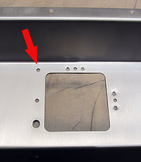
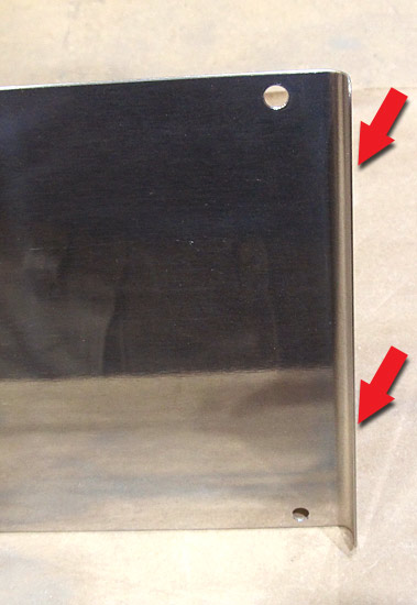
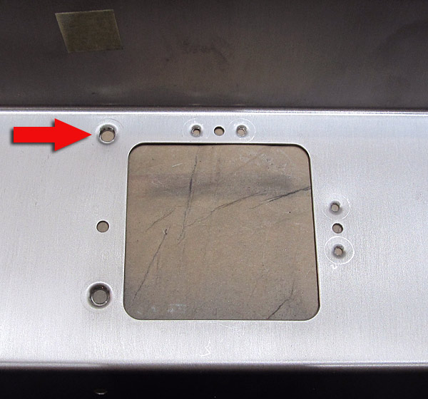 The "C" Clamp device did a nice job, the arrow points to the hole dimpled by the device and the hole at the bottom was done with our DRDT2 dimple machine. They are virtually the same in appearance! |
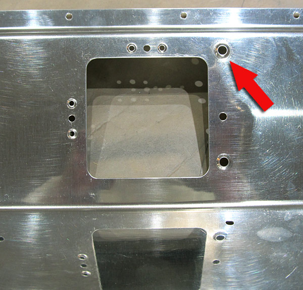 Here is what the "C" Clamp dimple looks like on the other side. |
 The #8 screws sit in the dimples nicely! |
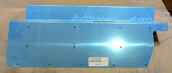 Now it's time to debur the edges on the (F-01436-R) right control column cover. |
 Back to the edge deburring.... |
 After the file work is done I like to polish the edges of the pieces with fine grit sandpaper. I usually start with 220 grit sandpaper and finish with 600 grit. |
 Nice! |
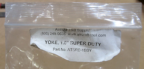 This is the 1.5" yoke for our hand held squeezer, I've had it for a long time but never needed to use it very much. |
 To change the yokes all you have to do is use a hammer and punch to remove the three roll pins and switch the yokes out. |
 The hand squeezer now has a 1.5" yoke installed! |
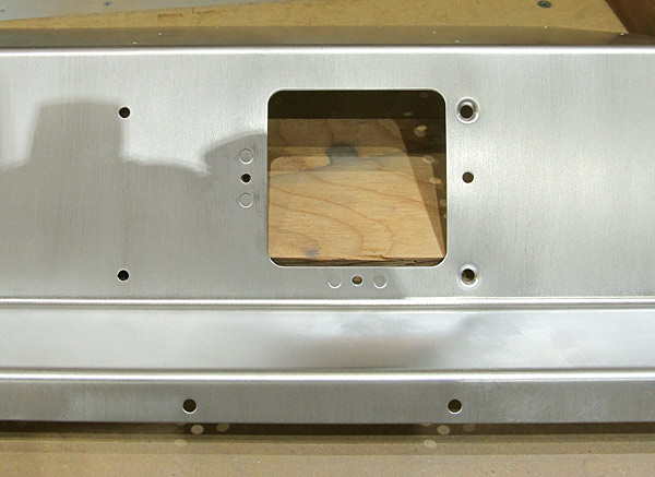
 As per step five, on page 42-02, referencing figure three, I dimpled the nutplate holes in the (F-01436-R) right control column cover using our hand rivet squeezer equipped with a 1.5" yoke. |
 The dimpling process went a lot faster on this (F-01436-R) right control column cover because I changed over to the 1.5" yoke. There is plenty of room to get the yoke into the space through the rectangular opening. |
 As per step five, on page 42-02, referencing figure three, I dimpled the #8 screw holes in the (F-01436-R) right control column cover using the hand rivet squeezer equipped with #8 screw dimple dies. |
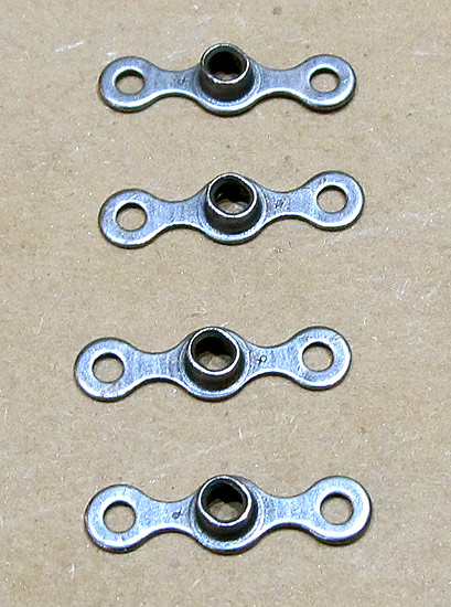 These four K1000-06 nutplates need to be dimpled. I will need to use a small diameter female 3/32" dimple die here because a regular sized one might be block by the center screw receiver post. |
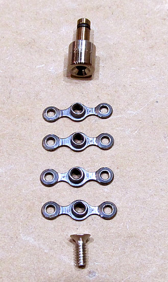 As per step five, on page 42-02, referencing figure three, the four K1000-06 nutplates were dimpled using our DRDT2 dimple machine equipped with one 3/32" male substructure dimple die set and one 3/32" small diameter female dimple die set. |
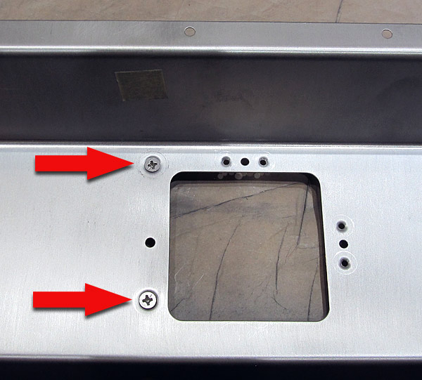
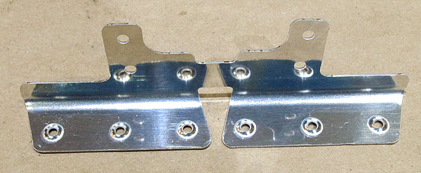
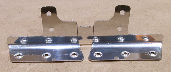
 As per step six, on page 42-02, referencing figure three, the K1000-06 nutplates were riveted to the (F-01436-L and F-01436-R) left and right control column covers with AN426AD3-3 rivets using our hand rivet squeezer. |
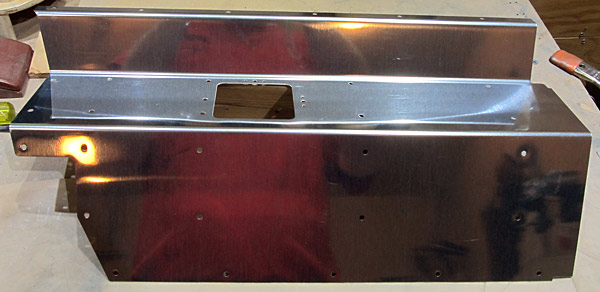
 I scuffed the (F-01436-R) right control column cover with maroon and gray Scotch-Brite™ pads in preparation for painting. |
 Here is a better picture of the scuffed (F-01436-R) right control column cover. Usually I do a quick wash of acetone to clean up the fine dust particles after the scuffing process. Later, just before painting, the piece will get a soap and water washing and degreased. |
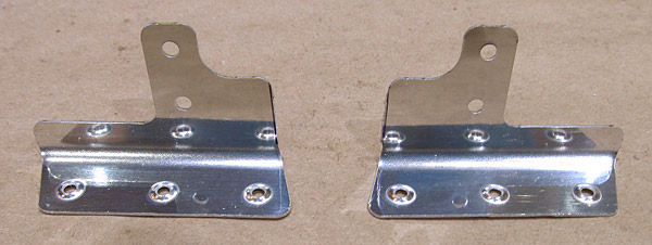
 Both of the (F-01436-L and F-01436-R) left and right control column covers have been scuffed. |
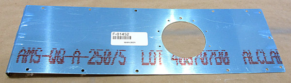 The (F-01452) aft tunnel cover is next in line for deburring. |
 I deburred the edges and all of the holes of the (F-01452) aft tunnel cover. |
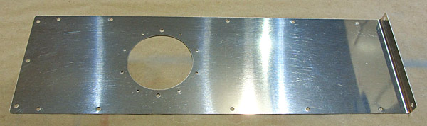
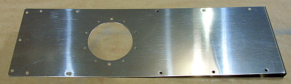 The edges of the (F-01452) aft tunnel cover were sanded and polished with various grits of sandpaper, starting with 220 grit and ending with 600 grit....I know, lots of extra work... |
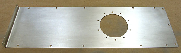 I scuffed the (F-01452) aft tunnel cover with maroon and gray Scotch-Brite™ pads in preparation for painting. |
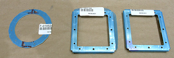 There are three small pieces that will be riveted in place on the different panels, the two (F-14114) control stick doublers, and the (F-01452A) aft tunnel cover doubler. |
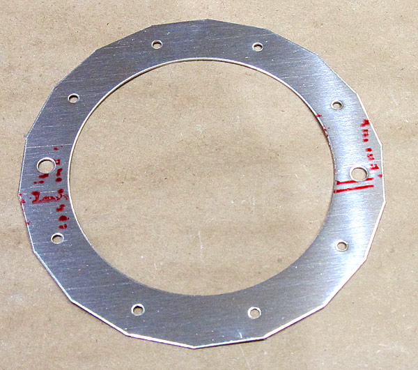 This is the (F-01452A) aft tunnel cover doubler. |
 I deburred the edges and all of the holes of the (F-01452A) aft tunnel cover doubler and scuffed all of the surfaces with maroon and gray Scotch-Brite™ pads in preparation for painting. |
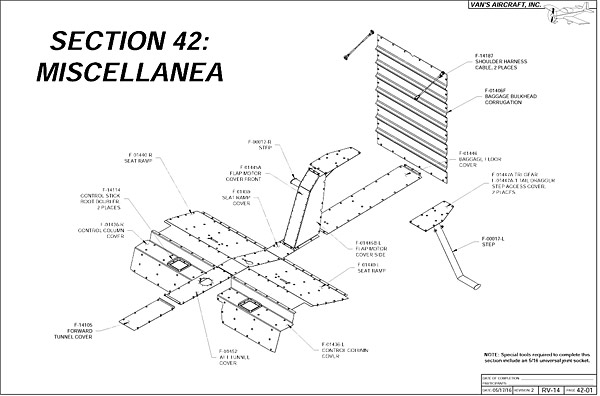 I just wanted to recap that I am in Section 42 called Miscellanea which is basically all of the access covers in the interior of the aircraft cabin plus the outside steps. |
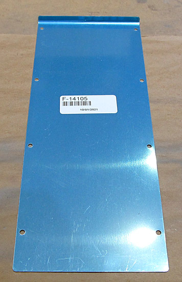 This is the (F-14105) forward tunnel cover. I start out with a file and debur the edges. |
 After I debur the edges I like to "polish" them with fine grit sandpaper. |
 All of the holes are deburred in the (F-14105) forward tunnel cover. |
 I scuffed the outer surface of the (F-14105) foward tunnel cover with maroon Scotch-Brite™ pads in preparation for priming. |
 These are the two (F-14114) control stick boot doublers. |
 The deburring process begins again starting with deburring the edges with a small file and all of the holes were deburred. |
 After deburring the edges and deburring all of the holes of the (F-14114) control stick boot doublers I polished the edges with fine grit sandpaper. |
 The surfaces of the two (F-14114) control stick boot doublers were scuffed with maroon Scotch-Brite™ pads in preparation for priming. |
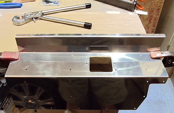
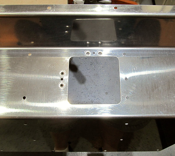
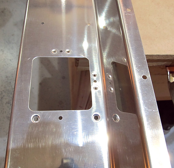
 As per step one, on page 42-07, and referencing figure one, the instructions mention that the holes in the (F-14114) control stick boot doublers need to be dimpled on the bottom sides so that the stick boots (not included in the kit) can be attached with AACQ 4-3 rivets (also not included in the kit). The question is, which holes need to be dimpled? I set up the (F-01436-L and F-01436-R) left and right control column covers onto the bench and then placed the two (F-14114) control stick boot doublers into position to figure this out. |
 Remember that in step six, on page 42-02, and referencing figure three, nutplates were installed onto the (F-01436-L and F-01436-R) left and right control column covers so these holes had to remain open. Knowing that the (F-14114) control stick boot doublers were held in place by three MS35206-228 screws and these three holes had to remain open, placing the control stick boot doublers in the proper orientation is important. |
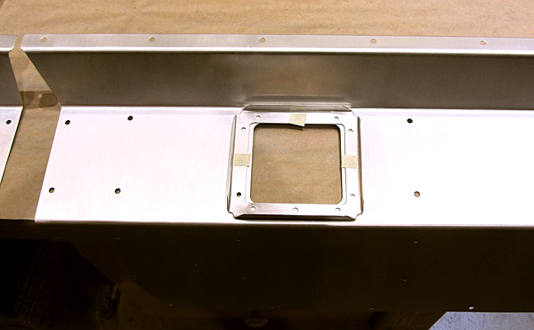 This is the left control column cover. |
 As per step one, on page 42-07, referencing figure one, the two (F-14114) control stick boot doublers were dimpled in the appropriate holes, and from the bottom side, in order to receive (AACQ 4-3) rivets. |
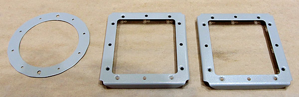 I primed the (F-01452A) aft tunnel cover doubler and the two (F-14114) control stick boot doublers with SPI (Southern Polyurethanes, Inc) 6610-4 gray epoxy primer. |
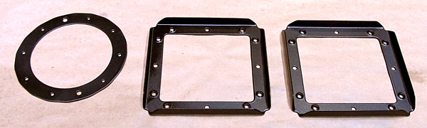
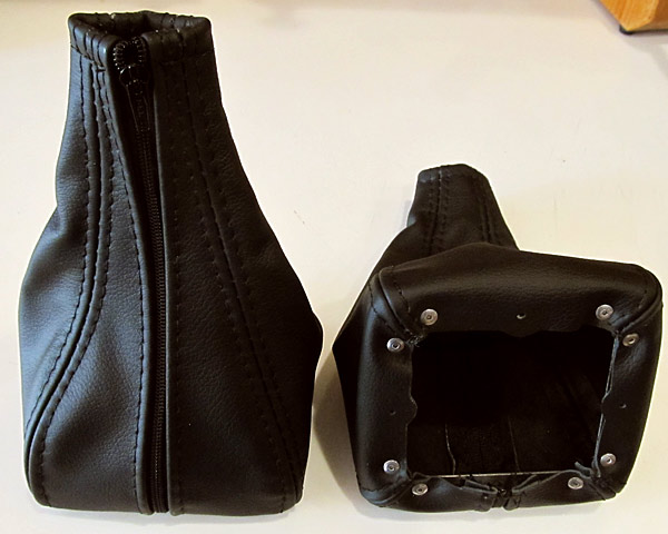 I ordered stick covers from Classic Aero Designs, located in Albany, Oregon and ironically if I had known that their stick covers came with the (F-14114) control stick boot doublers already attached, I would not have had to do all of the previous work on the stick boot doublers that came with the kit from Van's Aircraft. |
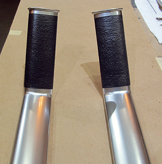
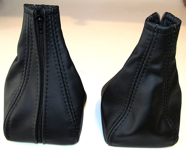 These stick covers are really nice and they are made of FAA approved leather. These are Orion/Raven colored, but you can order different colors from them. |
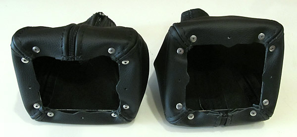 You can see the AACQ 4-3 rivets that hold the leather to the (F-14114) control stick boot doublers. |
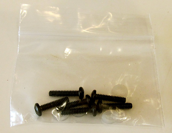 The MS35206-228 screws are included with the stick covers. |
 I painted the two (F-14114) control stick boot doublers and the (F-01452A) aft tunnel cover with Krylon Cover Maxx gloss black paint. |
 As per step one, on page 42-03 of the builder's manual and referencing figure one, I riveted the (F-01452A) aft tunnel cover doubler to the (F-01452) aft tunnel cover setting AN470AD3-3 rivets with our hand held squeezer. |
|
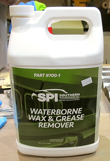 When I clean the bare metal parts in preparation for priming, I usually clean them with soap and water first and then use this SPI (Southern Polyurethanes, Inc.) waterborne wax and grease remover. |
 I cleaned and degreased the (F-01406F) baggage bulkhead corrugation with the SPI waterborne wax and grease remover in preparation for priming. |
 I cleaned and degreased the (F-01446) baggage floor cover with the SPI waterborne wax and grease remover in preparation for priming. |
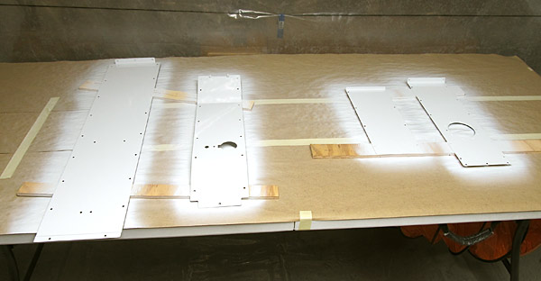
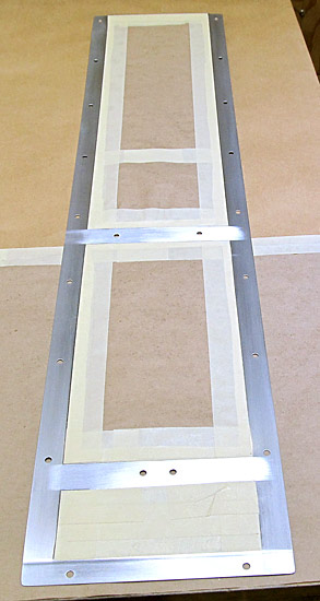 I masked the centers of the (F-01446) baggage floor cover and also the (F-01406F) baggage bulkhead corrugation, in order to expose the edges, in preparation for priming. |
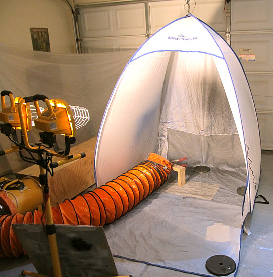
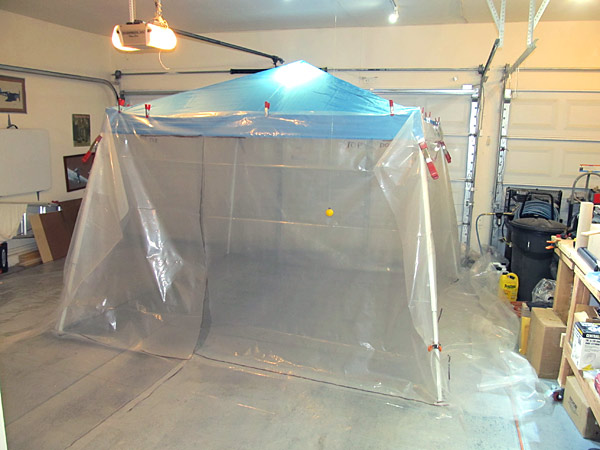 This is my large paint booth that I use in the garage to paint some of the medium sized parts. |
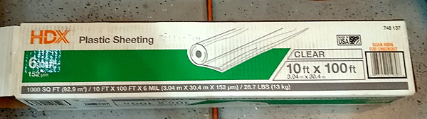 I clamp 6 mil plastic sheeting, that I bought from Home Depot, to cover the sides and bottoms in order to contain the overspray of paint. |
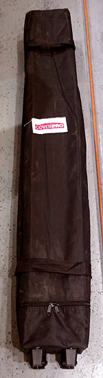 When I am done using the paint booth, I fold it up and it is stored in the wheeled storage bag that was included in the pop-up canopy kit. |
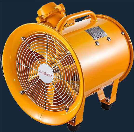 To exhaust the booth when I am painting, I use a Vevor 12 inch explosion proof fan. |
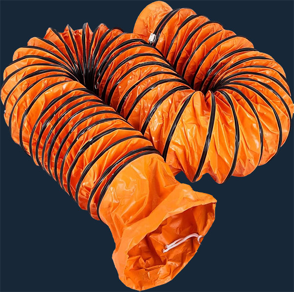 This is the 12 inch x 25 foot Vevor PVC flexible duct hosing that I am using to vent between the paint booth and the exhaust fan. |
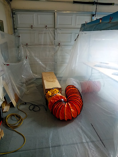 Here you can see the exhaust set up... |
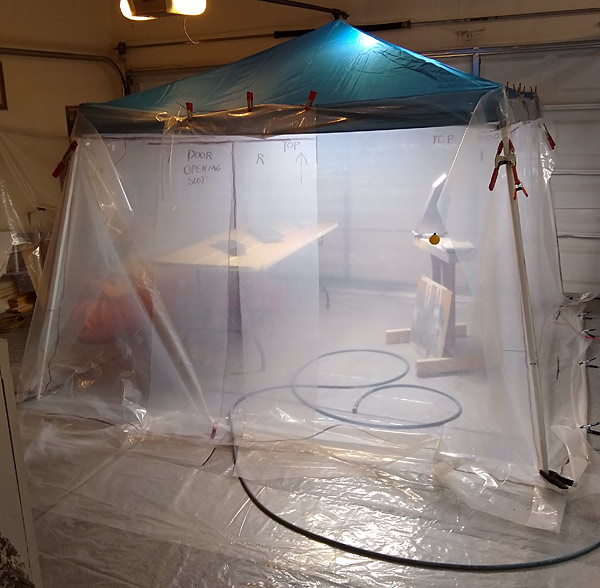 Here is the booth in use, I use a light unit from Harbor Freight to light the booth. |
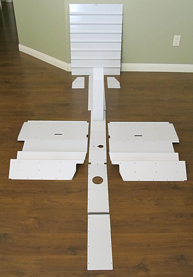
 I primed the following parts with SPI (Southern Polyurethanes, Inc.) 6610-4 gray epoxy primer: |
 (F-01406F) front side of baggage bulkhead corrugation |
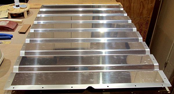
 All of the parts were sanded and scuffed before painting with Stewart Systems Ekocrylic waterborne E5301 smoke gray. |
 The seat back brace assemblies and the seatback assemblies were painted with Stewart Systems waterborne Ekocrylic E5301 smoke gray paint. |
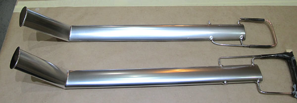
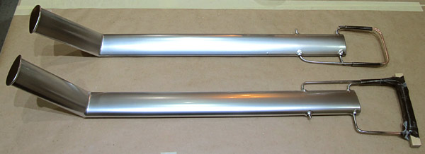
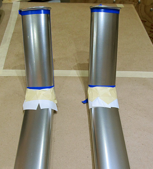
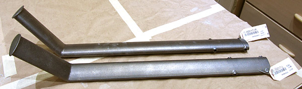 The (F-00017-L and F-00017-R) left and right steps are made of 4130 chromium molybdenum alloy steel. They are very hard and strong but the texture is grainy and rough. I want to sand and smooth them out in preparation for painting. I am using silicon carbide sandpaper so that I do not get dissimilar metal contamination. I am starting out with 150 grit sandpaper. |
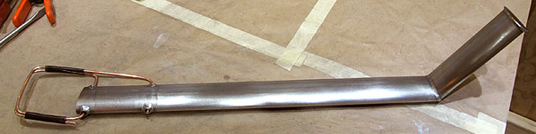 I sanded the (F-00017-L) left step first, starting out with 150 grit silicon carbide sandpaper and working up through the grits to at least 400 grit so that when I apply the primer and topcoat paints I'll get a super smooth finish....the idea is not to have to use any heavy fillers as well. I also fashioned a heavy copper wire rod to hold the step and manuever it as I paint it in the paint booth. |
 Now to sand the (F-00017-R) right step. |
 If you look closely, you can see the textured surface of the step, I still need to get this one a little smoother for painting. |
 I finished sanding the (F-00017-R) right step. Now it is time to clean the steps with soap and water and then wax and degrease them with the degreaser. |
 I washed and degreased the two steps with SPI (Southern Polyurethanes, Inc.) 700-1 waterborne wax and grease remover. |
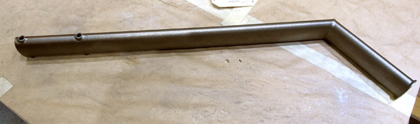
 I am priming the (F-00017-L and F-00017-R) left and right steps with SPI (Southern Polyurethanes, Inc.) 6610-4 gray epoxy primer. |
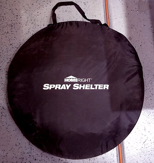 This spray booth folds up into a small carrying bag when not in use. |
 I painted the (F-00017-L and F-00017-R) left and right steps with UTECH 500 gloss black paint. |
 I painted the (F-00017-L and F-00017-R) left and right steps with Alclad ALC 107 chrome. |
 In order to protect the finish I painted the (F-00017-L and F-00017-R) left and right steps with three coats of Alclad ALC 310 clear lacquer at 22 psi. |
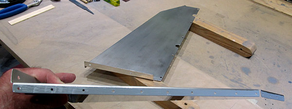
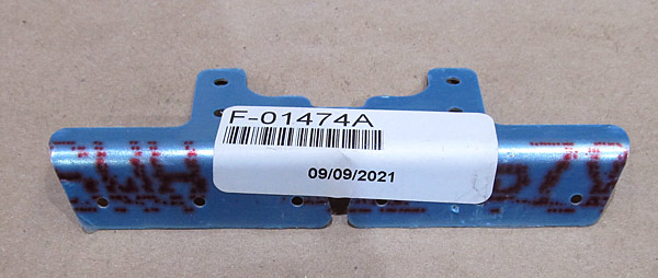 As per step one, on page 38-04, referencing figure one, the (F-01474A-L and F-01474A-R) left and right stiffener angles need to be dimpled to accept (AN426AD3-4) rivets. |
 I am using 3/32" dimple dies and our DRDT2 dimple machine to dimple the stiffeners. |
 *Make sure to reference figure one on page 38-04 so that the correct side of the (F-01474A-L and F-01474A-R) stiffener angles are dimpled. |
 I drew layout lines onto the (F-01474A-L and F-01474A-R) stiffener angles because in step two, on page 38-04, figure one, they need to be separated into two parts. |
 I used a bandsaw to separate the (F-01474A-L and F-01474A-R) stiffener angles. |
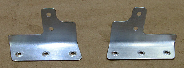 All of the holes and edges of the (F-01474A-L and F-01474A-R) left and right stiffener angles were deburred and the surfaces were scuffed with a maroon Scotch-Brite™ pad in preparation for painting. |
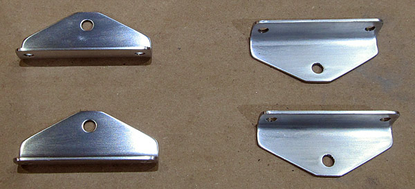
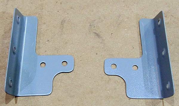
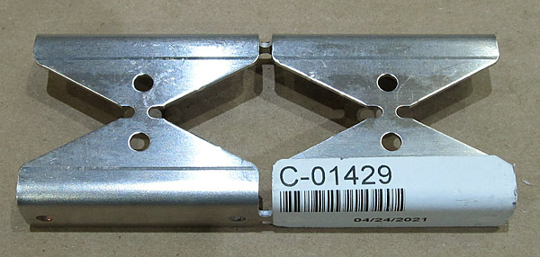 The (C-01429) latch bellcrank angles need to be separated next... |
 As per step ten, on page 38-04, figure three, I separated the (C-01429) latch bellcrank angles into four parts using our bandsaw. |
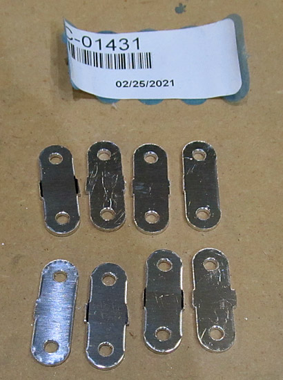
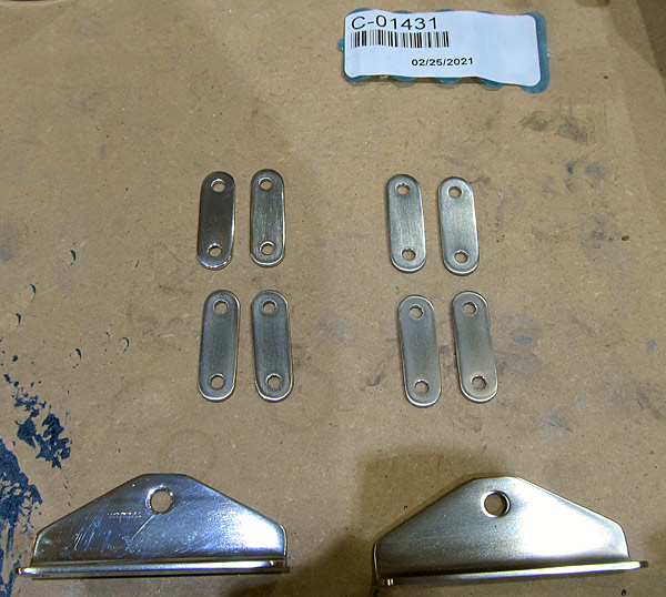
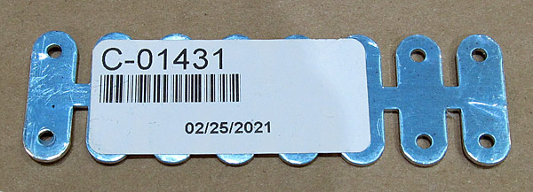 The (C-01431) latch links need to be separated. |
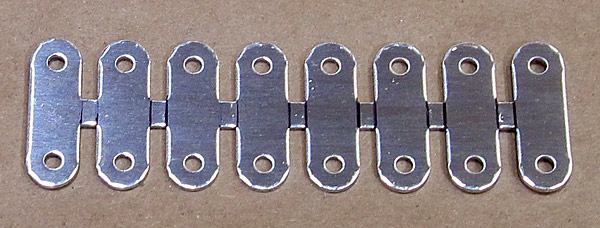 I drew layout lines onto the (C-01431) latch links to guide the cutting process on the bandsaw. |
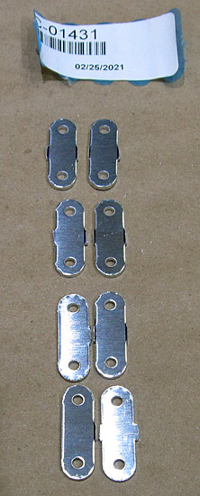 As per step eleven, on page 38-04, figure four, I separated the (C-01431) latch links into eight parts using our bandsaw. |
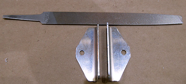 I am deburring the edges and holes of the (C-01429) latch bellcrank angles. I always start out with a small file and then finish off with sandpaper. |
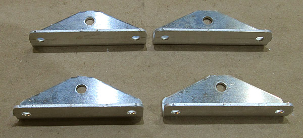
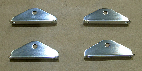
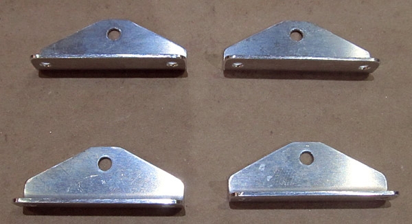 The edges of the four (C-01429) latch bellcrank angles that were separated in step ten, on page 38-04, figure three, and the holes, were deburred. |
 I am going to polish these four (C-01429) latch bellcrank angles because they will be visible in the cockpit area so it is going to start with sanding them smooth with fine grit sandpaper. |
 The sanding process starts out with 320 grit sandpaper and continues up to 15000 grit sandpaper. |
 The eight (C-01431) latch links are small so getting them ready to polish will be a challenge. I first start out with the small file to debur the edges and debur the holes. |
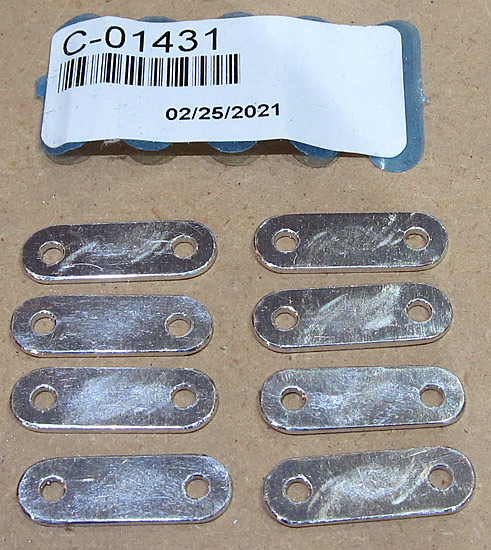 The edges of the eight (C-01431) latch links have been deburred and sanded, and now comes the tedious task of polishing them. |
 I primed the (F-01474A-L and F-01474A-R) left and right stiffener angles with SPI 6610-4 gray epoxy primer. |
 The eight (C-01431) latch links that were separated in step eleven, on page 38-04, figure four, are in the sanding phase of being polished. |
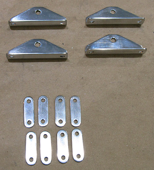 The top four (C-01429) latch bellcrank angles have had some polishing done on the buffing wheel. |
 I painted the two (F-01474A-L and F-01474A-R) stiffener angles with Stewart Systems Ekocrylic E5465 Royal Blue, which is the same color that the roll bar assembly is painted. |
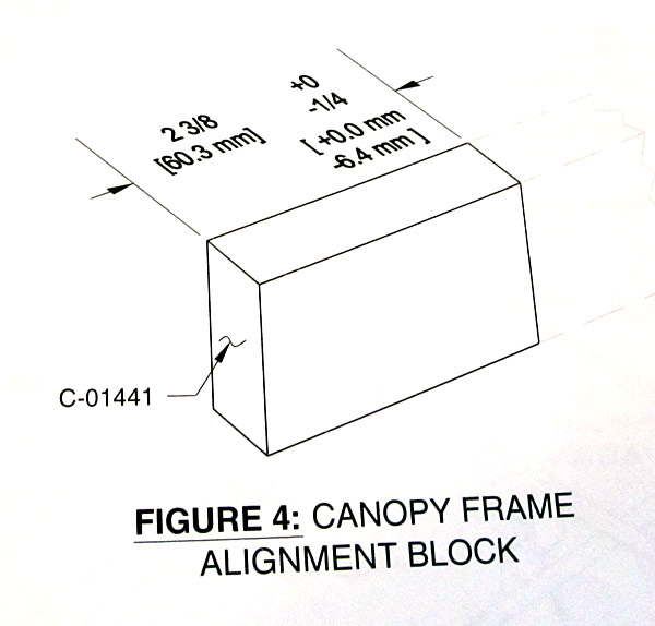 Since I had the miter saw out working on another project I thought I would jump ahead to step six, on page 38-19, figure four and fabricate the four (C-01441) canopy frame alignment blocks. |
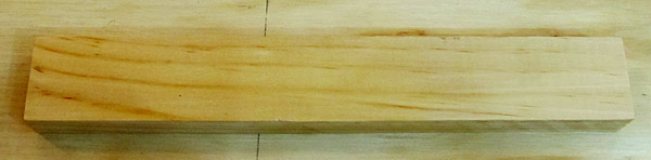 The (C-01441) canopy alignment blocks are cut out from one piece of wood supplied in the kit. This is what it looks like before cutting the blocks. |
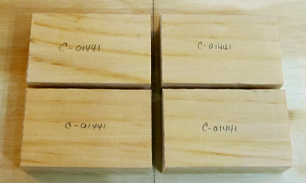 Four (C-01441) canopy frame alignment blocks! |
 The (F-01474A-L and F-01474A-R) left and right stiffener angles are positioned at the base of the roll bar assembly so part of the stiffener angle is painted royal blue, to match the roll bar color, and the other half of the stiffener angle is riveted onto the aft fuselage top side skins, which is smoke gray. |
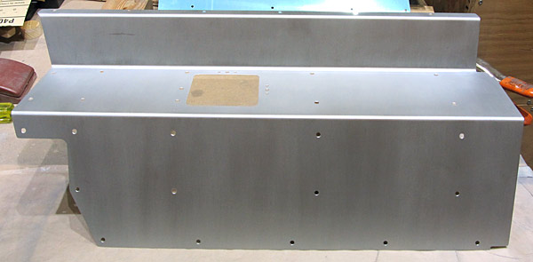
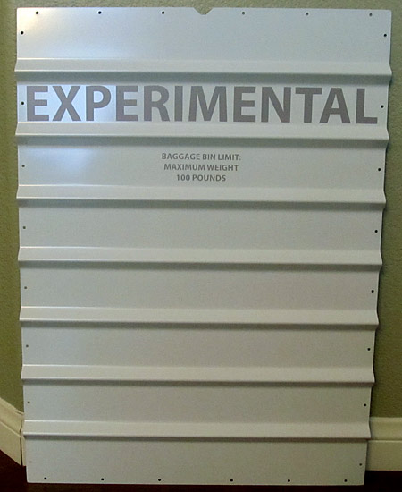 I applied the required "Experimental" placard to the (F-01406F) baggage bulkhead corrugation. |
 The second half of the two (F-01474A-L and F-01474A-R) left and right stiffener angles were painted with Stewart Systems E5301 Ekocrylic smoke gray paint. |
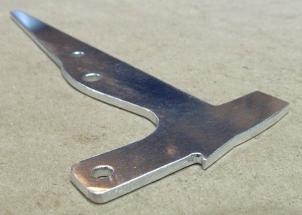
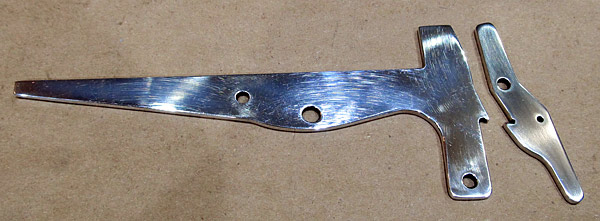
 As per step one, on page 38-05, I checked the flatness of the (C-607) latch handle. |
 As per step one, on page 38-05, I checked the flatness of the (C-609) canopy latch. |
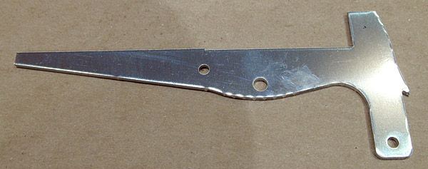 As per step two, on page 38-05, figure one, I am deburring the edges of the (C-607) latch handle. |
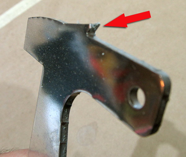 This (C-607) latch handle had a small chip in the catch; I was able to file it flat and was a little worried if the mechanism would function correctly but thankfully everything functions well! |
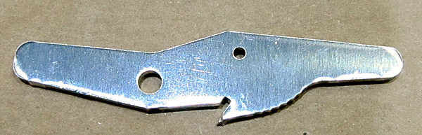 The (C-609) canopy latch is next for deburring. The edges on this is just as rough as the latch handle is.... |
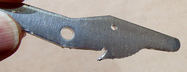 *Don't forget to inspect the notch on the (C-609) canopy latch, mine had a small chip in the notch also. |
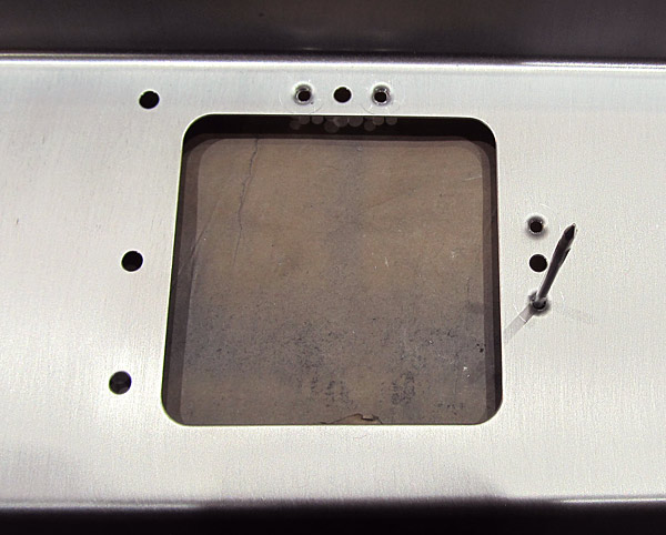
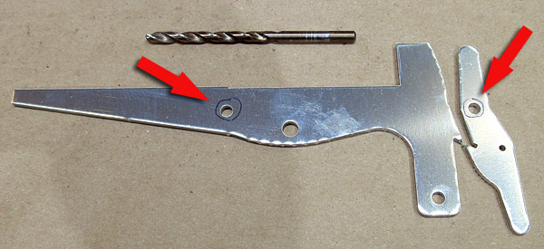 As per step three, on page 38-05, figure one, there are two holes on the (C-607 and C-609) latch handle and canopy latch that need to be final drilled #12 size. The photograph shows these holes circled with a sharpie pen. |
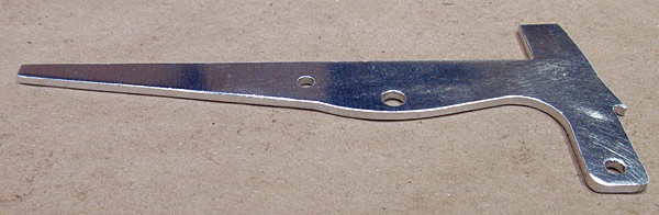 Back to deburring the edges on the (C-607) latch handle.... |
 I deburred the edges of the (C-607) latch handle and am now starting to sand them smooth. |
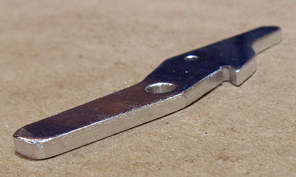 The edges and the holes have been deburred on the (C-609) canopy latch. |
 Remember the chips in the notches of the (C-607 and C-609) latch handle and canopy latch? |
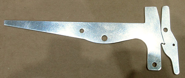
 The edges on the (C-607) latch handle and the (C-609) canopy latch have been final sanded and polished. |
 The surfaces on the (C-607) latch handle and the (C-609) canopy latch have been final sanded and ready to be polished. |
 I polished the (SL-3) with Nuvite NuShine IIS, it is a final grade metal polishing compound. |
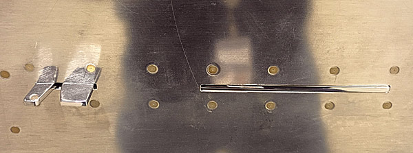
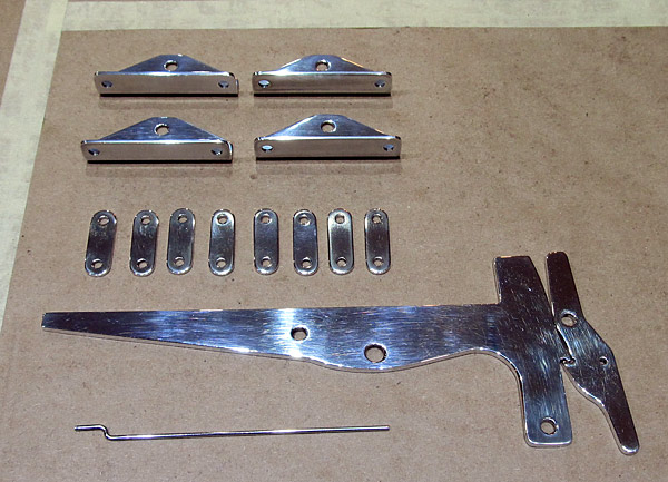 These are the canopy and door latching parts, they have been polished with Nuvite NuShine IIA polishing compound "grade A" which is a fine metal polishing compound used just before the final mirror finish compound Nuvite NuShine IIS. |
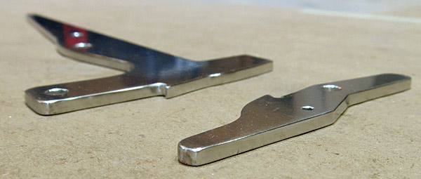
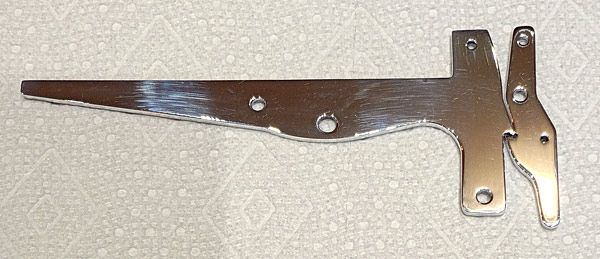 The (C-607) latch handle and the (C-609) canopy latch have been polished with Nuvite NuShine IIS final metal polishing compound. |
 The (F00017-L and F-00017-R) left and right steps are masked off so that they can be painted with wing walk material. |
 I painted the treads on the (F00017-L and F-00017-R) left and right steps with Randolph's wingwalk paint. |
 This is what two coats of the Randolph's wingwalk mixture looks like when fully dried. |
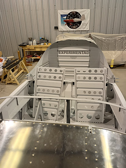 I temporarily installed the (F-01406F) baggage bulkhead corrugation after applying the "Experimental" placard to the aft portion of the baggage bin. |
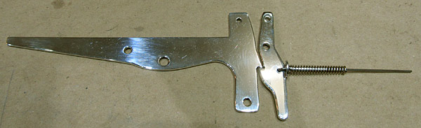
 As per step eight, on page 38-05, figure one, I installed the door latch mechanism to the fuselage to check for fit and function. |
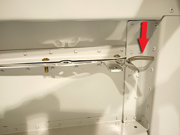 This is what I mean when I mention the flex of the (C-615) spring. There is supposed to be a modification that can take care of this and make everything work in a more "solid" action. |
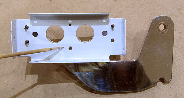
 This is what the door latch mechanism looks like from the exterior of the fuselage. |
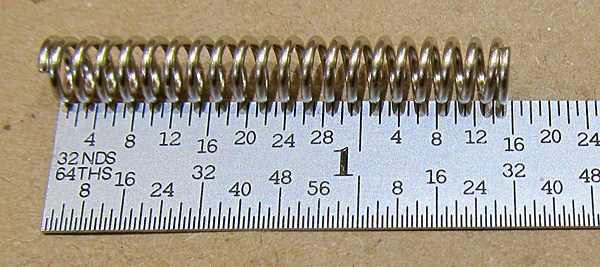 This is the (C-615) door latch spring. |
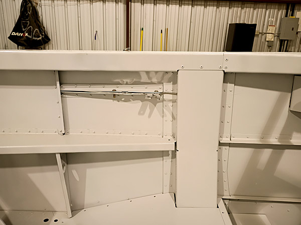
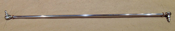
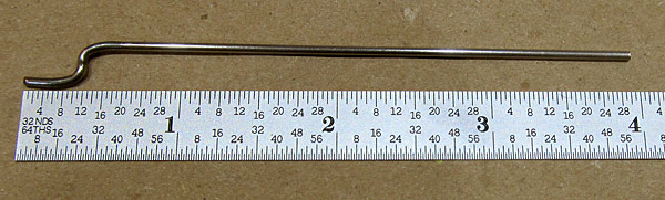 The (SL-3) rod is part of the latching mechanism, it connects to the (C-609) canopy latch through the (C-615) spring to a hole in the (F-01487-L) center section channel. The rod is more or less a guide to keep the mechanism in alignment. |
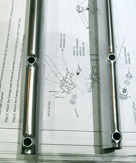
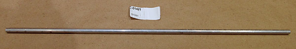 This is the (C-01421) canopy latch pushrod. It connects the door latch assembly to the canopy latch torque tube assembly which engages the canopy latch pins to lock the canopy when flying. |
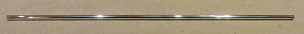 I polished the (C-01421) canopy latch pushrod with Nuvite NuShine IIS metal polishing compound. |
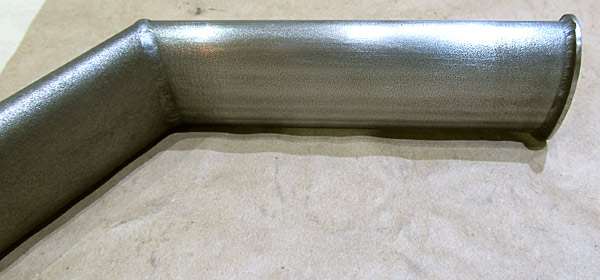
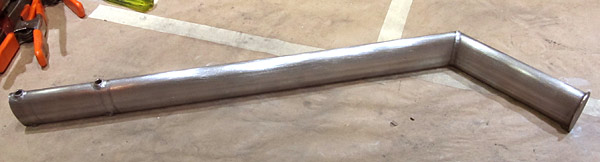
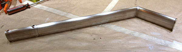
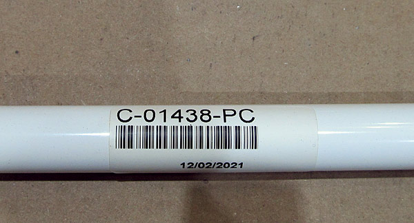 This is the (C-01438) canopy latch torque tube. |
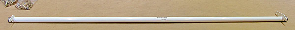 The (C-01438) canopy latch torque tube is 42 7/8" long. |
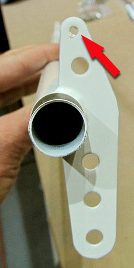 As per step ten, on page 38-05, figure three, the 1/8" hole on the (C-01438) canopy latch torque tube needs to be final #30 drilled. |
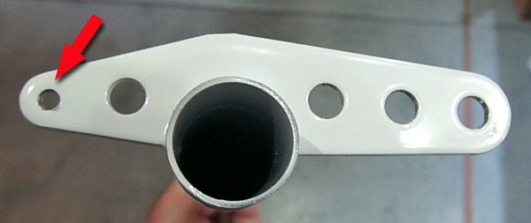 The 1/8" holes were final #30 drilled and deburred on each side of the (C-01438) canopy latch torque tube. |
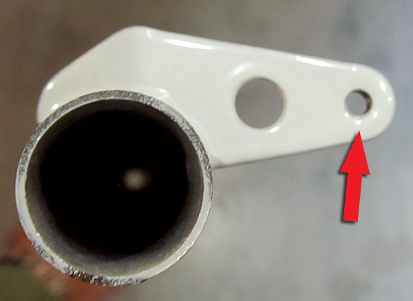 Additionally according to figure three, on page 38-05, there is a 1/4" hole that needs to be final drilled, it is only on the left side. |
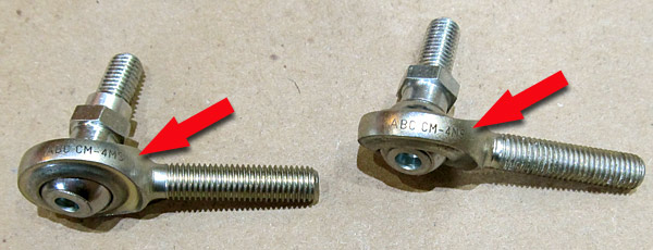 As per step thirteen, on page 38-05, figure four, there needs to be two (CM-4MS) bearings attached to the ()1421) canopy latch pushrod. |
 As per step thirteen, on page 38-05, figure four, the Canopy Latch Pushrod Assembly was fabricated by attaching the two (CM-4MS) angular bearings to the (C-01421) canopy latch pushrod and clocking them 90° from each other at a length of 20 13/16". |
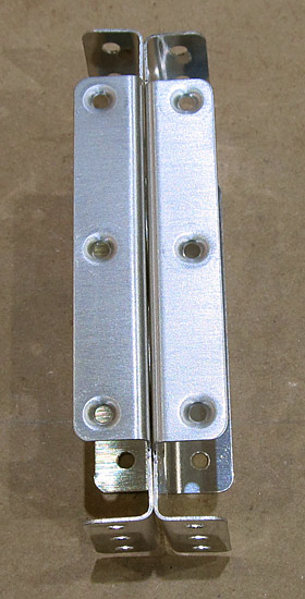
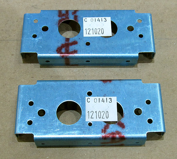 The edges and the holes need to be deburred on the (C-01413) inboard hinge intercostals. There are two of these. |
 The edges and the holes of the (C-01413) inboard hinge intercostals were deburred. |
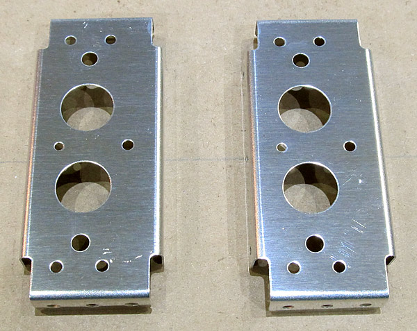
 The surfaces of the (C-01413) inboard hinge intercostals were scuffed with maroon Scotch-Brite™ pads in preparation for priming. |
 As per step eight, on page 38-06, figure two, the top flanges of the two (C-01413) inboard hinge intercostals, were dimpled with 3/32" reduced diameter female dimple die sets using our hand squeezer. |
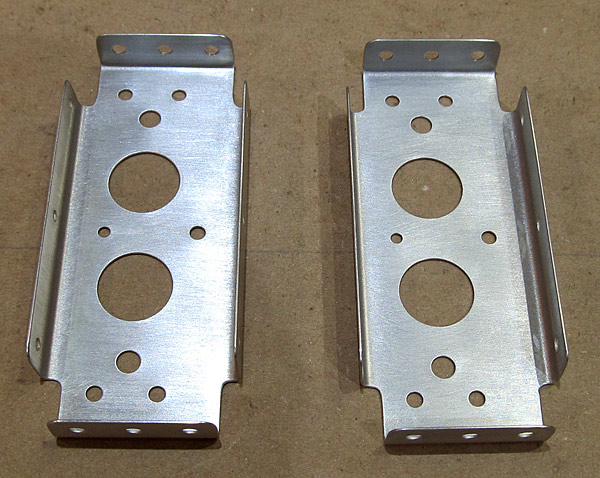
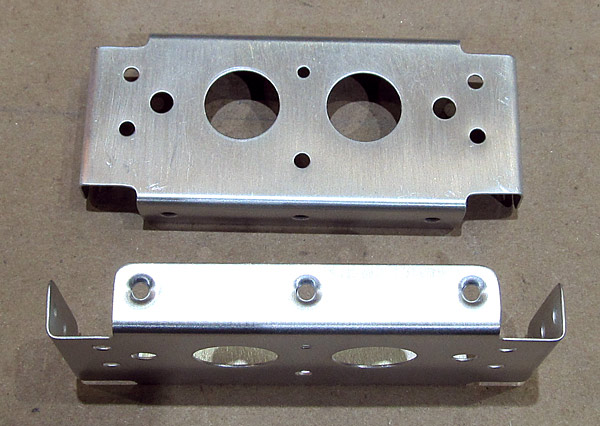
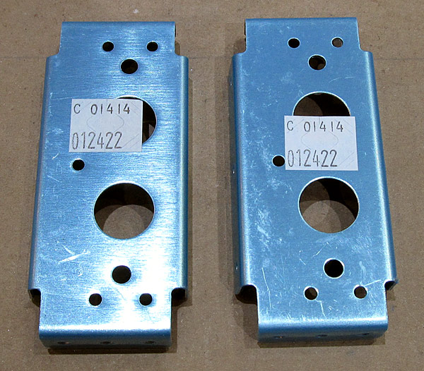 The two (C-01414) outboard hinge intercostals need to be deburred. |
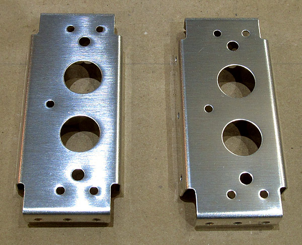 The edges and the holes were deburred. |
 As per step eight, on page 38-06, figure two, the top flanges of the (C-01414) outboard hinge intercostals were dimpled with 3/32" reduced diameter female dimple die sets using a hand squeezer. |
 The surfaces of the (C-01414) outboard hinge intercostals were scuffed with maroon Scotch-Brite™ pads in preparation for priming. |
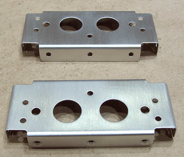
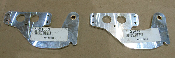 These are the two (C-01412) canopy hinges. They need to be deburred and I have elected to polish them to a mirror finish. |
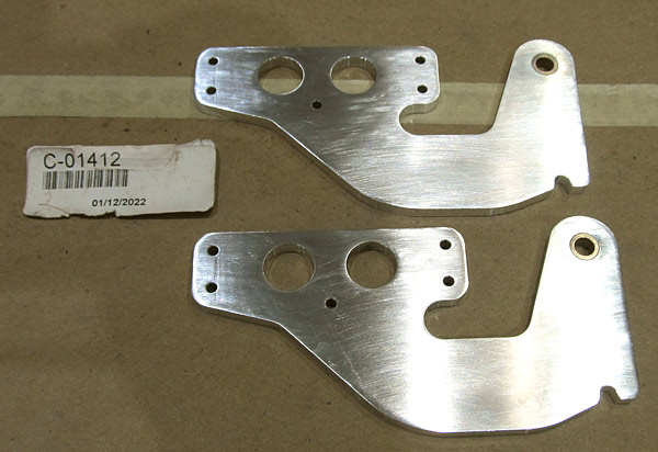 As I began to sand the surfaces for polishing I noticed that there was a shallow groove on each of the hinges (you can see them on the left part of the tab in this photograph). |
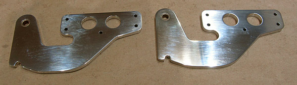 I start with 320 grit sandpaper and end with 15000 grit and then final polish with Nuvite NuShine IIS metal polish. This is about the 5000 grit portion of the sanding. |
 I primed the (C-01413 and C-01414) inoboard and outboard hinge intercostals with SPI 6610-4 gray epoxy primer. |
 The (C-01412) canopy hinges are still being sanded to 15000 grit sandpaper and will soon be ready to be polished with Nuvite NuShine IIA and IIS polishing compound. |
|
As I explained earlier I didn't like the way that the (C-615) spring "kinked" when it was in position in the canopy latch assembly. |
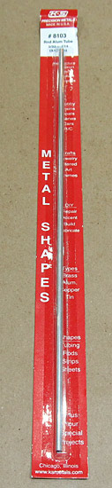 First I need to get some aluminum tubing, at first I thought that 5/32" diameter tubing would work but it was too wide so I ended up using 1/8" tubing which fit better inside the (C-615) spring. |
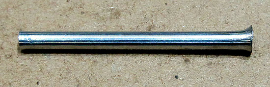 Next, one end of the tubing needs to be flared, I used a dowel rod to make the flare. The aluminum is soft enough to make the flare but it does take some effort to get the job done....not too hard, not to soft. |
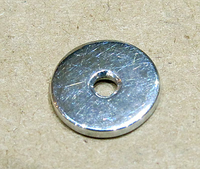 This is a stop washer that will prevent the flared aluminum tube to ride up over the (C-609) canopy latch. |
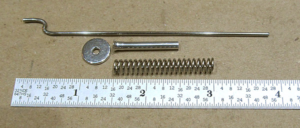 These are all of the parts for the modification, everthing was polished with Nuvite NuShine IIS metal polish. |
 This is how everything goes together, I need to install it onto the airframe and check the function... |
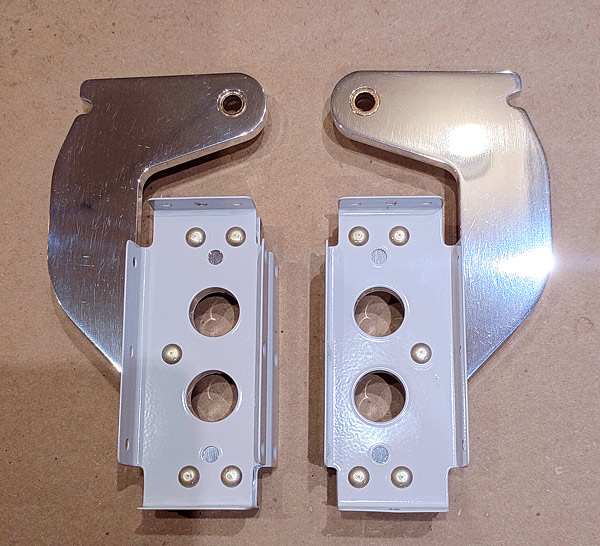
 As per step nine, on page 38-06, figures three and four, the (C-01413) inboard hinge intercostals and the (C-01414) outboard hinge intercostals were clecoed to the (C-01412) canopy hinges so that they could be riveted together with AN470AD4-8 rivets. |
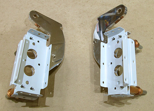 The smaller #40 hole defines the inside half of the canopy hinge assembly so double check how everything is clecoed together before riveting. |
 Before I rivet the canopy hinge assemblies together I wanted to final size the holes in the (F-00017-L and F-00017-R) steps. |
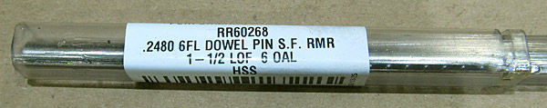
 The holes in the (F-00017-L and F-00017-R) steps were final sized using a .2480" ream on the drill press. |
 Back to the riveting... |
 This is the piece that the (C-01406) forward canopy rails are separated from. |
 I used a sharpie pen to lay out the cut lines and separated them using a bandsaw. |
 As per step one, on page 38-07, figure one the two pieces were separated. Now there is (C-01406-L) left foward canopy rail and a (C-01406-R) right forward canopy rail. |
 As you can see, the bandsaw cut needs to be filed and deburred and the material is thick. |
 The edges and all of the holes were deburred on the (C-01406-L) left forward canopy rail. I also used 220 grit sandpaper to smooth out the edges. |
 The (C-01406-R) right forward canopy rail is next to be deburred. As you can see, the edges are rough and when I cut them on the bandsaw I cut just a little wide of the line so there is plenty of file work to do at first. |
 The edges and all of the holes on the (C-01406-R) right forward canopy rail have been deburred and smoothed with 220 grit sandpaper. |
 I will probably sand the edges on the (C-01406-L and C-01406-R) left and right forward canopy rails up to 400 grit sandpaper. |