 The hardware callout in figure three, page 36-03 says that the (CS-00001) forward elevator pushrod, (CS-00002) mid elevator pushrod, and the (CS-00003) aft elevator pushrod need to be assembled using MSP-42 rivets, depending which bag you pull them from this is what they look like.
|
 I clecoed the rod end fittings onto the ends of each elevator pushrod making sure to match the previously marked end to it's corresponding torque tube.
(CS-00001 and CS-00002) forward and mid elevator pushrods each receive (CS-00016) rod end fittings while the aft elevator pushrod (CS-00003) receives a (VA-101) rod end fitting.
|
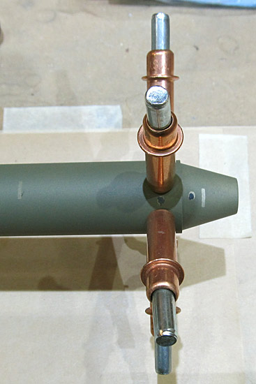 This is the forward elevator pushrod (CS-00001) ready to receive attachment of the (CS-00016) rod end fitting.
*You can see the markings I used so that when I reassembled the piece after priming I could put everything back in the right order.
|
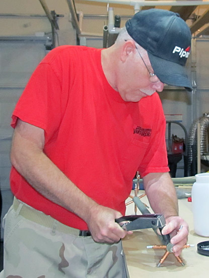 I used our CherryMax G-27 hand rivet gun to set the MSP-42 rivets.
|
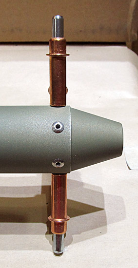 Two rivets set, 34 more to go! Each end receives six rivets.
|
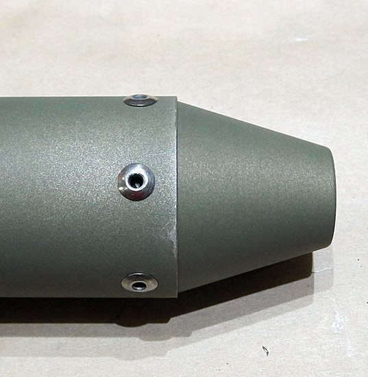 Nice!
|
 The rod end fittings have been attached to each of the three elevator pushrods (CS-00001, CS-00002, and CS-00003).
|
 The rod end bearings are next to be installed onto each of the elevator pushrods. There are two jam nuts and two rod end bearings per pushrod to be assembled; the hardware callouts are shown in figure 3, page 36-03 for the forward and mid elevator pushrods and in figure 3, page 36-04 for the aft elevator pushrod.
Basically, the (CS-00001) forward elevator pushrod and the (CS-00002) mid elevator pushrod receive two AN316-4R jam nuts and two M3414M rod end bearings each. The (CS-00003) aft elevator pushrod receives two AN316-6R jam nuts and two MD3616M end bearings.
*Be sure to take note of the warning that states that "in the final installation both pushrod ends must have over half of the threads engaged making it impossible for a bearing to back off the pushrod if both ends are pinned."
|
 Once the jam nuts and the rod end bearings have been installed, the overall lengths must be adjusted.
Figure 4, page 36-03 of the builder's manual shows the bearing-to-center bearing lengths that each of the forward and mid elevator pushrods should theoretically be.
This is the (CS-00001) forward elevator pushrod and I adjusted it so that it had a bearing-to-center bearing length of 31 11/16". I tightened the jam nut, for now, only finger tight because most likely there will be further adjustments needed upon actual installment at which time the jam nut will be torqued and safety sealed into place.
*Keep in mind that as you adjust the pushrods to their final length you must adjust each end evenly until final length is achieved.
|
 This is the (CS-00002) mid elevator pushrod and I adjusted it to a bearing-to-bearing center length of 44 15/16" with the jam nut tightened only finger tight until final installation at which time it will be final torqued and safety sealed.
|
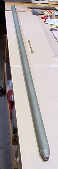 The (CS-00003) aft elevator pushrod receives two AN316-6R jam nuts and two MD3616M rod end bearings as called for referencing figure 4, page 36-04 of the builder's manual.
*The same note warning that "in the final installation both pushrod ends must have over half of the threads engaged making it impossible for a bearing to back off the pushrod if both ends are pinned applies here too."
|
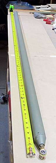 According to the dimensions given in figure 4, page 36-04 of the builder's manual, the bearing-to-bearing center length should theoretically be 72 29/32" so I adjusted it accordingly and then finger tightened the jam nut in place.
*The jam nut will be final torqued and sealed after final installation.
|
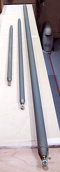 All of the elevator pushrods have their jam nuts and rod end bearings installed and have been adjusted for proper length.
|
 The stick link pushrod assembly (CS-00004) connects the two flight control sticks together and is assembled in a somewhat similar fashion as the elevator pushrods.
In step 4, page 36-02 of the builder's manual, the assembly process begins. Figure three gives the hardware callouts which consist of two AN316-4R jam nuts and two M3414M rod end bearings.
The bearing-to-bearing center length was adjusted to 21 1/2" according to the measurements given on the same page. The jam nuts were tightened finger tight but will be final torqued and sealed when installed.
|
 We are installing an autopilot on our RV14A and I ordered the optional Garmin autopilot servo install kit from Van's Aircraft. Step one, on page 56-02 of the builder's manual instructs that two pushrods and one roll standoff be fabricated from a (AT6-058x5/16) aluminum tube.
|
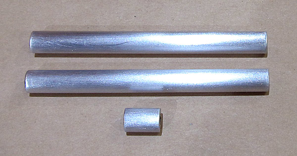 The two push rods created are 3 1/4" in length and will be labled (CS-00017) for the pitch control rod, (CS-00019) for the roll control rod, and (CS-00020) for the roll servo standoff, (which is 15/32" long).
I cut these out using the bandsaw and then squared the ends using a stationary disc sander. The ends were deburred as well.
|
 Now the fun begins...
Figure one, page 56-02 of the builder's manual, gives additional information in the construction of the two (CS-00017 and CS-00019) autopilot pitch and roll pushrods.
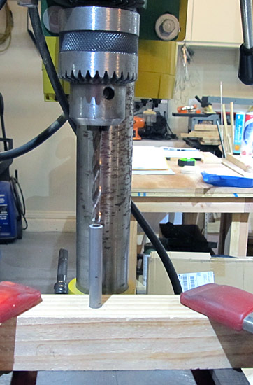
A #3 hole is to be drilled through the center of each end of each tube to a depth of 1 1/4". Obviously this needs to be centered as much as possible so I constructed a simple jig by drilling a 5/8" hole in a scrap piece of 2"x4" lumber with the drill press in order to hold the tube vertically. This made it easy to keep the tube centered while drilling the #3 hole down the center of the tube with our drill press.
*Make sure you don't drill the 5/8" hole all the way through the 2"x4" wood because you need the tube to be able to rest on the bottom flat area of the wood, plus the extra friction helps keep the tube from spinning as the #3 hole is being drilled in the tube.
|
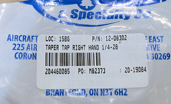 After the 1 1/4" #3 hole has been drilled in both ends of the tubes they need to be threaded using a 1/4-28 tap to a depth of 1 inch.
|
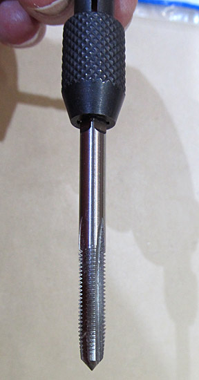 I will be using a hand set and this 1/4-28 tap to thread both ends of the (CS-00017 and CS-00019) autopilot pitch and roll servo pushrods.
|


 It took 8 months, almost to the day, from the time we ordered the quickbuild kits until we received them at our hangar.




 I riveted the tie down doublers to the


 Lots of Clecos!
 Okay, Let's start riveting!


 The outside of the fuselage was masked off in preparation for priming.
 The bare metal areas in the baggage area that were previously scuffed were washed with acetone.
 The bare metal areas in the baggage area were primed with
 The cockpit floors were primed as well.


 Trust me, the cockpit area is all smoke gray in color, the lighting is playing tricks on the camera!


